



Contents: Removal 🠛 Installation 🠛
- The ten-piece fuel rail protectors isolate the high-pressure injection system from the engine compartment.
- For the system to function properly, it must consist of the following elements:
- two porous gaskets (1, Fig. 4.63), subject to replacement if they are damaged or soaked with diesel fuel;
- a lower protective element (2) made of sheet steel and secured between the fuel distribution line and the cylinder head;
- diesel fuel return pipes;
- a rubber apron (3) attached to the sheet metal protective element and to the cylinder head cover;
- two side partitions (4);
- partitions (5) fixed to the cylinder head cover;
- two holders (6).
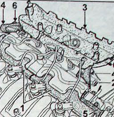
Fig. 4.63. Fuel distribution line protection elements: 1 - porous pads; 2 - lower protective element; 3 - rubber apron; 4 - side partitions;5 - partition; 6 - holder
- When performing any work with the fuel distribution line protection elements, care must be taken to ensure that after installing all the elements that make up this system, the latter are installed precisely in place.
Removal
- Disconnect the cable from the negative terminal of the battery
- Disconnect the connector from the air flow sensor.
- Remove the air filter housing and the engine compartment bulkhead sound insulation. To remove the sound insulation, it is necessary, without disconnecting, to remove the turbocharger pressure control electromagnetic valve installed on the engine compartment bulkhead.
- Remove the expansion tank mounting bracket by disconnecting the pre-heating and post-heating unit.
- Remove the fuel line at the turbocharger inlet by disconnecting the crankcase ventilation system hose.
- Remove the side partitions of the rubber apron. Disconnect from the engine mount, then from the cylinder head cover and move the rubber apron back as much as possible.
- While holding the studs, remove the two nuts, remove the cylinder head cover sealing partition and remove the porous absorbent pads.
- Disconnect the connector from the pressure sensor (1. Fig. 4.58).
- Disconnect the rubber hose (2) of the diesel fuel return from the injectors.
- Remove the fuel injection pipes (3) connecting the high-pressure pump and the fuel distribution line. When removing the retainer (6) installed on the cylinder head, be careful, as it is very fragile.
- When unscrewing the union nut (1. Fig. 4.59) to secure the fuel injection tube to the injector body, use the second key to hold the filter mounting nut (2). Seal the holes with plugs.
- Loosen the bolts (5, Fig. 4.58) the fuel distribution line fasteners and the line mounting flange bolt on the lower sheet metal protective element, and then remove the line with the side partition.
- Disconnect the diesel fuel return pipe (1. Fig. 4.64).
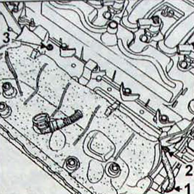
Fig. 4.64. Location of the diesel fuel return pipe (1) and bolts for fastening the side bulkhead (2) and the lower sheet metal protective element (3)
- Remove the bolt (2) securing the side partition.
- Remove the bolt (3) securing the lower protective element made of sheet metal.
- Remove the main line protection with the side partition, and then remove the center partition.
- Remove the rubber apron from the lower sheet metal guard.
Installation
- Install the rubber apron onto the lower sheet metal guard using the five rubber retainers (1. Fig. 4.65). Make sure the rubber clips are securely installed
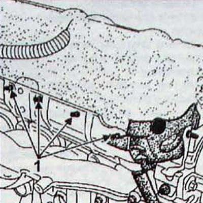
Fig. 4.65. Location of rubber clamps (1)
- Install the rubber apron assembly/sheet metal lower guard onto the engine.
- Install the side partition onto the lower sheet metal guard, making sure to follow the following procedure:
- secure the bottom loop (1. Fig. 4.66); - place the rounded rubber part of the partition onto the lower sheet metal protective element;
- place the top of the partition on the sheet metal protective element;
- secure the top loop (1, Fig. 4.67);
- screw in the bolt (2) for fastening the partition;
- connect the diesel fuel drain pipe (3), making sure that it is not blocked.
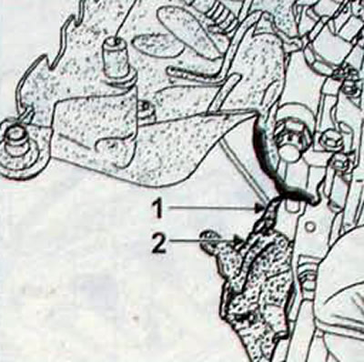
Fig. 4.66. Location of installation of the lower hinge (1) and the rounded rubber part of the partition (2)
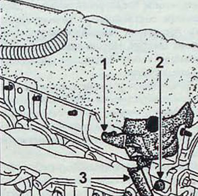
Fig. 4.67. Location of installation of the upper hinge (1), bolt (2) for fastening the partition and the drain pipe (3) of diesel fuel
- Install the fuel distribution line with the partition without tightening the line mounting bolts.
- Remove the plugs from the main line, injector housings, pump and fuel injection lines.
- Connect the fuel lines of the injectors between the main line and the injectors, having first tightened the connections between them by hand until they touch.
- Tighten to torque:
- 23 H-m three fastening bolts of the main line;
- 25 Nm fuel injection line fittings at the injectors and at the high pressure pump;
- 25 Nm fuel injection line fittings at the main line.
- Install absorbent foam pads, replacing them if they are damaged or soaked with diesel fuel.
- Install the sealing partition in place, securing it with two nuts on the cylinder head cover.
- Make sure the label is installed correctly (1. Fig. 4.68) highway partitions (along the axis of the high-pressure fuel outlet lines of the main line)
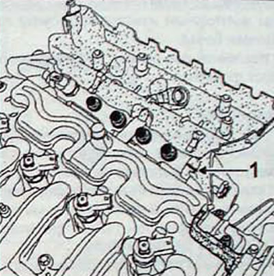
Fig. 4.68. Location of the mark (1) of the main partition
- Connect the connectors to the injectors and the line pressure sensor.
- Install the new diesel fuel return line, making sure that the mounting clamps are in place at the injectors and at the end of the line at the overpressure valve
- Move the rubber apron forward and attach the side sealing partitions to it.
- Make sure that the partitions are securely fastened with clamps and that the rubber apron skirts are positioned correctly
- Attach the rubber apron to the cylinder head cover and engine mount. Make sure that the apron is securely fastened with clamps to the cylinder head cover and engine mount.
- Use a diagnostic tool to check for any recorded fault codes in the memory and, if any, clear them, and make sure the diesel fuel return pipe is securely connected.
- After performing any work, check for leaks in the diesel fuel supply circuit. Let the engine idle until the electric cooling fan comes on, then increase the engine speed several times while idling. Perform a road test. Turn off the ignition and check the car for diesel fuel leaks. Check that the porous gaskets are not soaked with diesel fuel.