



The operation of the brakes is also affected by the condition of the tires, the vehicle load and the alignment angles of the front wheels.
Checking the operation of the vacuum booster
Release any vacuum with the engine off by depressing the brake pedal several times at 5-second intervals. With the brake pedal fully depressed, start the engine. Make sure that the gap between the brake pedal and the floor panel decreases as the engine vacuum stabilizes.
Checking for leaks
Start the engine and let it idle for about 1 minute. Shut it off by applying vacuum to the booster. Press the brake pedal several times with normal force and release the existing vacuum. Make sure that when you press the brake pedal, the gap between the brake pedal and the floor panel gradually increases. Start the engine. Press the brake pedal and hold it down, then shut off the engine. Keep the pedal depressed for about 30 seconds or more and make sure that the pedal travel does not change.
Removal
Remove the decorative covers.
Disconnect the wires from the battery terminals, starting with the negative terminal.
Remove the battery.
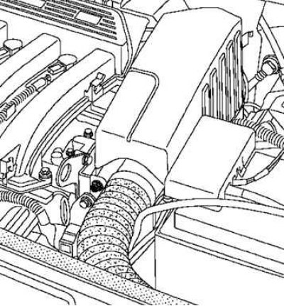
Fig. 6.16. Removing the air resonator
Remove the air resonator (only for K4J engine) (Fig. 6.16).
Remove the battery tray.
Remove the injection system ECU.
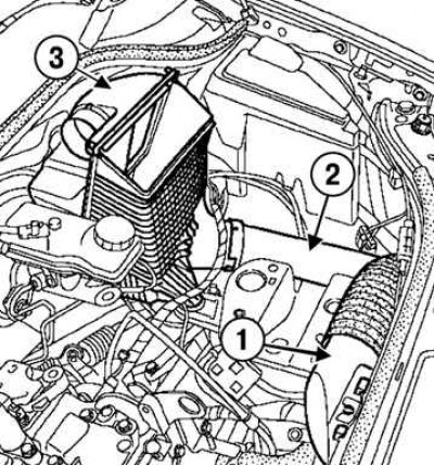
Fig. 6.17. Removing the air filter components: 1 – air intake pipe; 2 – air pipe; 3 – air filter housing
Remove the air intake pipe, air pipe and air filter housing (Fig. 6.17).
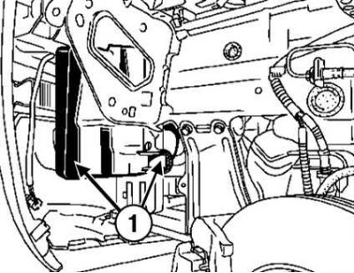
Fig. 6.18. Removing the intake noise mufflers: 1 – mufflers
Remove the left front wheel, mudguard and both intake silencers (Fig. 6.18).
Disconnect the gear selector and shift cables from the transmission.
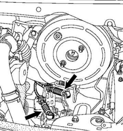
Fig. 6.19. Gear selection and shift cables
Disconnect both cables from the levers on the gearbox (Fig. 6.19).
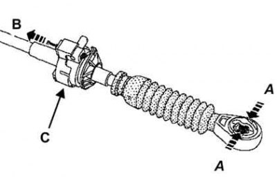
Fig. 6.20. Method of removing the gear selection cable tip
Squeeze the end of the cable at points A, pull the clamp in direction B and lift the cable at point C (Fig. 6.20).
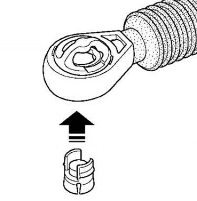
Fig. 6.21. Installing plugs in the ends of the gear selection cables
Insert the plugs into the ends of the gear selector cables (Fig. 6.21).
Remove the brake pedal switch.
Remove the brake fluid from the reservoir using a syringe until its level is below the fluid supply hole in the clutch master cylinder.
Disconnect the brake fluid level sensor connector.
Remove the brake booster vacuum take-off valve.
Partially remove the noise insulation from the front shield.
Disconnect the clutch master cylinder line.
Remove the upper ball joint of the transmission control mechanism.
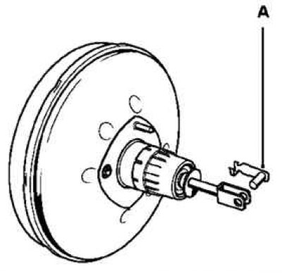
Fig. 6.22. Removing the brake pedal fork axle
Remove the brake pedal fork axle A from the brake booster pushrod from the passenger compartment side (Fig. 6.22).
Remove the two nuts securing the master cylinder to the brake booster.
Tilt the master cylinder forward to separate it from the booster without applying force to the brake lines.
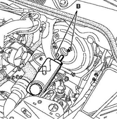
Fig. 6.23. Removing the vacuum booster: B – Brake booster mounting bolts
Remove the two brake booster B mounting bolts (Fig. 6.23).
Installation
Installation is carried out in the reverse order of removal.
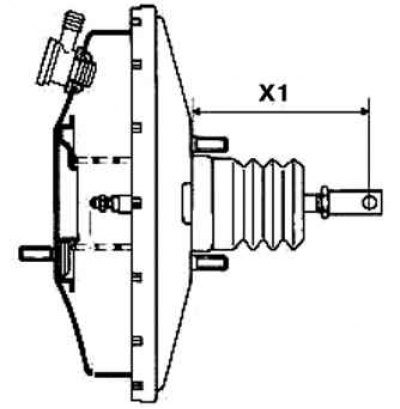
Fig. 6.24. Measuring the length of the vacuum booster fork rod
Before installation, measure the length of the fork stem (Fig. 6.24):
- for left-hand drive vehicles: X1 = 163.7 mm;
- for right-hand drive vehicles: X1 = 133.2 mm.
If the length is not as specified, replace the amplifier.
Caution! Check the presence and locking of the connecting axis between the brake booster pushrod and the brake pedal.
Install the brake booster without securing the pushrod to it.
Tighten the two brake booster mounting bolts to 21 N·m.
Install the master cylinder to the brake booster.
Tighten the two brake master cylinder mounting nuts to 50 Nm.
Check the position and reliability of fixation of the holder C on the front shield and the brake pipes in this holder.
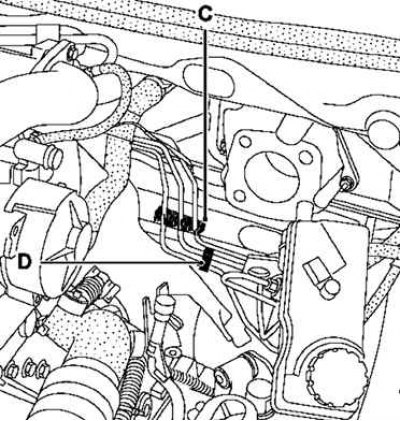
Fig. 6.25. Checking the reliability of the holders
Make sure the spacer holder D is in place.
From the passenger compartment side, install the push rod into the brake booster and onto the brake pedal.
Press the brake pedal to connect the pushrod and booster.
Reinstall the brake pedal fork axle.
Make sure that the brake pedal fork axle is securely fixed to the pushrod.
Reinstall the brake pedal switch.
Check the operation of the brake pedal limit switch (the brake lights should go out when the brake pedal is released).
Add brake fluid.
Replace the master cylinder reservoir cap.
Install the remaining removed parts in the reverse order of removal.
Connect the wires to the battery terminals, starting with the positive terminal.
Perform a road test.