
English Русский
Български
Беларускі
Український
Српски
Hrvatski
Română
Polski
Slovenský
Magyar
Bookmark Contacts Articles Sitemap
Company vehicles Peugeot Company vehicles Opel Company vehicles Skoda Company vehicles Land Rover Company vehicles Mitsubishi Company vehicles Volkswagen Company vehicles Honda
RenaultBook.ru


Duster   Fluence   Kangoo   Laguna   Logan   Megane   Sandero   Scenic   Symbol   Clio   Other
Megane 1 (1995-2002) Megan 2 (2002-2009, petrol)

General information about the braking system (Renault Megane 2)

  • Main
  • Megane
  • Megan 2 (2002-2009, petrol)
  • Chassis, running gear
  • Brake system
  • General information about the braking system
0
Contents: Vacuum brake booster 🠛 Master brake cylinder 🠛 Pressure regulator 🠛 Brake fluid level sensor 🠛 Brake system fittings and pipes 🠛 Brake fluid 🠛
The car is equipped with two diagonally located brake circuits. One circuit uses the front right and rear left wheels, the second - the front left and rear right wheels. When only one of the circuits is working, you have to press the brake pedal harder to achieve braking of the car. In this case, the pedal travel increases, and the braking distance is lengthened.

When you press the brake pedal, the pusher presses on two pistons of the master brake cylinder, which, through the brake booster, generate pressure in the system.

The main brake cylinder is not repairable. If it fails, it must be replaced as an assembly. The pistons transmit the pedal force via a hydraulic line to the brake calipers.

The support pushes the piston of the wheel cylinder, which in turn presses the pads against the brake disc. When the pedal is released, the piston returns to its original position and the pads move away from the disc. The distance between the pads and the disc is 1 mm, but this is enough for the disc to rotate freely.
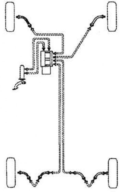
Fig. 6.1. Diagram of a brake drive with diagonal separation of circuits

Fig. 6.1. Diagram of a brake drive with diagonal separation of circuits


Vacuum brake booster


The vacuum brake booster reduces the force on the brake pedal, making it easier to drive. The vacuum amplifier uses a diaphragm, which creates a vacuum on both sides during normal operation. When braking, air is applied from one side of the diaphragm, forming atmospheric pressure. Due to the pressure difference transmitted through the diaphragm, the pusher moves in the direction of vacuum (vacuum), providing an auxiliary force for braking. When the brake pedal is released, air is pumped out of the booster cavity through the control valve, creating a vacuum.
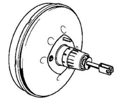
Fig. 6.2. Brake booster

Fig. 6.2. Brake booster


Master brake cylinder


The brake master cylinder is used on dual circuit brake systems. The front right and rear left brake mechanisms are actuated by the primary piston, and the front left and rear right are actuated by the secondary piston. The brake master cylinder combines the functions of a standard dual brake master cylinder, as well as a low brake fluid indicator and a brake pressure regulator.

Fig. 6.3. Master brake cylinder

Fig. 6.3. Master brake cylinder


Pressure regulator


The pressure regulator limits the output pressure to the rear brakes after the pressure has reached the maximum value in the master cylinder. The regulator is used when less force is required to be applied to the rear brakes to achieve optimum braking.

Brake fluid level sensor


The brake fluid level sensor, located in the brake fluid reservoir, turns on the BRAKE indicator lamp when it detects a low fluid level. Once the brake fluid reaches the required level, BRAKE goes out.

Brake system fittings and pipes


The connection of the pipes between the master brake cylinder, brake calipers and hydraulic block is carried out by means of threaded fittings with metric threads.
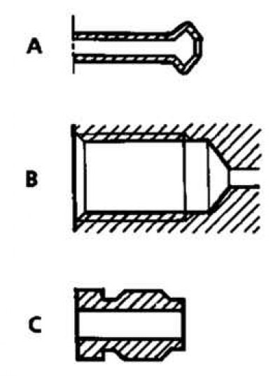
Fig. 6.4. Identification of brake system nipples: A – shape of steel or copper tube tips; B – shape…

Fig. 6.4. Identification of brake system nipples: A – shape of steel or copper tube tips; B – shape of threaded recesses in nodes; C – fittings with six outer edges of 11 mm each


Brake fluid


Brake technology and, in particular, disc brakes (hollow pistons that transfer little heat, small amount of fluid in the cylinder, floating calipers that eliminate the need for a relatively large reserve of working fluid in the least cooled part of the wheel), allows to minimize the risk of "vapor locks" even in case of frequent and prolonged use of brakes (in the mountains). However, the characteristics of the brake fluid deteriorate somewhat during the first months of operation due to slight absorption of moisture. This causes the need to replace the brake fluid.


Table 6.1. Technical characteristics of brake system components
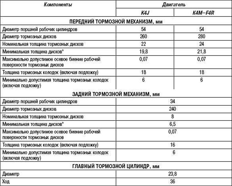


Table 6.1. Technical characteristics of brake system components
This article is available on: russian, bulgarian, belarusian, ukrainian, serbian, croatian, romanian, polish, slovak, hungarian
Article has been reviewed by editor: Kupriyanov Sergey
Share with friends:
 
Megan 2: Brake system
Next

 
Frequency of brake fluid replacement
Bleeding air from the hydraulic drive of the service brake system
Bleeding the pressure control circuit
Removal and installation the master brake cylinder
Checking, removing and installing the brake booster
Other articles on other Renault models

➽ General information about the braking system Renault Fluence 1 (2009-2020, petrol)
➽ Anti-lock braking system Renault Kangoo 1 (1997-2007)
➽ Emergency braking system Renault Laguna 2 (2001-2007)
➽ Checking the efficiency of the braking system Renault Logan 1 (2004-2012, petrol)
➽ Checking the efficiency of the braking system Renault Sandero 1 (2007-2012, petrol)
Link to this article in different formats
Reviews and comments of visitors
No comments yet


Add two numbers 26 + 35


Megan 2 (2002-2009, petrol) 
  • User manual
  • Introduction to manual
  • Controls and instruments
  • Salon equipment
  • Operation and driving
  • Maintenance and care
  • Power unit
  • Engine repair
  • Fuel system
  • Injection system
  • Intake and exhaust system
  • Starting and charging system
  • Cooling system
  • Decreased toxicity
  • Transmission
  • Clutch
  • Mechanical gearbox
  • Automatic gearbox
  • Wheel drive mechanism
  • Chassis, running gear
  • Suspension and wheels
  • Steering
  • Brake system
  • Body and interior
  • Exterior (external elements)
  • Interior (internal elements)
  • Doors, locks and windows
  • Heating and air conditioning
  • Electrical equipment
  • Equipment and devices
  • Headlights and lighting
  • Electrical circuits
Megane 1 (1995-2002) 
  • General information
  • User manual
  • Maintenance
  • Power unit
  • Petrol engines 1.4/1.6 l
  • Petrol engines 2.0 l
  • Diesel engines 1.9 l
  • Overhaul of engines
  • Cooling system
  • Fuel system (petrol)
  • Fuel system (diesel)
  • Decreased toxicity
  • Charge and launch systems
  • Ignition system (petrol)
  • Preheat system (diesel)
  • Transmission
  • Clutch
  • Mechanical gearbox
  • Automatic gearbox
  • Drive shafts
  • Chassis, running gear
  • Brake system
  • Car suspension
  • Steering
  • Body and interior
  • Exterior (external elements)
  • Interior (internal elements)
  • Doors, locks and windows
  • Electrical equipment
  • Equipment and devices
  • Electrical circuits
RenaultBook.ru © 2018–2026 | Mobile version | News and articles | Sitemap: EN BG BY UA RS HR RO PL SK HU | Administration | Site search | Bookmark
Duster 1 (2009-2017) | Fluence 1 (2009-2020, petrol) | Kangoo 1 (1997-2007) | Laguna 2 (2001-2007) | Logan 1 (2004-2012, petrol) | Logan 2 (2012-2020) | Megane 1 (1995-2002) | Megan 2 (2002-2009, petrol) | Sandero 1 (2007-2012, petrol) | Scenic 1 (1996-2003) | Symbol 1 (1999-2008, petrol) | Symbol 2 (2008-2013, petrol) | Renault 19 (1988-1996) | Espace I and II (1984-1996) | Espace III (1996-2002) | Clio 1 (1990-1998) |
We want your visit to be comfortable 😌 and use cookies 🍪 to do so.