



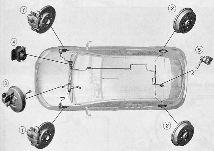
Brake system components:1. Front disc brakes. 2. Rear drum brakes. 3. Vacuum brake booster with master brake cylinder. 4. Hydro-electronic fjr-jr ABS control. 5. Brake force compensator.
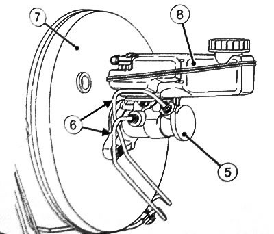
Brake drive:5. Master brake cylinder. 6. Brake lines between the master brake cylinder and the hydraulic electronic control unit. 7. Brake booster. 8. Brake fluid reservoir.
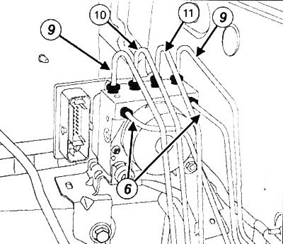
ABS hydro-electronic control unit: 9. Connecting brake pipe hydro-electronic unit-body bottom. 10. Brake pipe hydro-electronic unit-front left brake mechanism. 11. Brake pipe hydro-electronic unit-front right brake mechanism.
The vehicle uses a braking system with duplicate diagonal circuits.
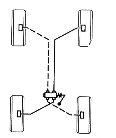
Schematic diagram of a brake system with a load-sensing brake force compensator
Caution: The brake system diagrams shown are for general purposes only. Do not use the diagram as a reference for determining connection points or routing brake lines. When replacing brake system components, be sure to apply alignment marks before removing them.
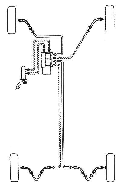
Diagram of the brake system with ABS