
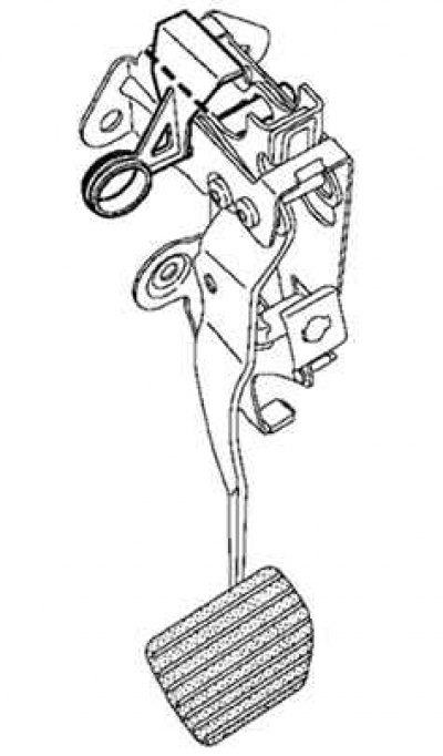
Removing the pedal
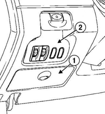
Pic. 6.37. Removing the glove box and headlight range control switch: 1 - glove box; 2 – the switch of the corrector of the direction of light of headlights
Disconnect the glove box, rear headlight range control switch and disconnect the headlight range control switch panel connectors (pic. 6.37).
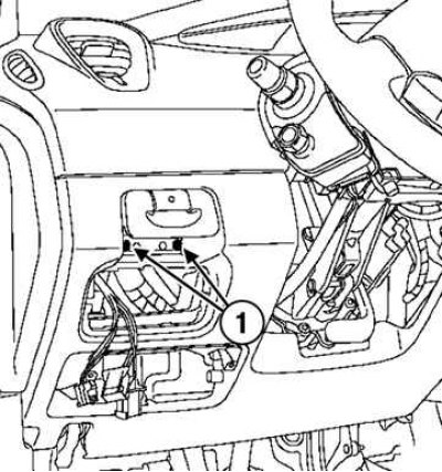
Pic. 6.38. Unscrewing the screws securing the automatic parking brake control handle: 1 - screws
Remove the screws securing the automatic parking brake control knob (pic. 6.38).
Disconnect the connectors on the automatic parking brake control knob.
Remove the control knob.
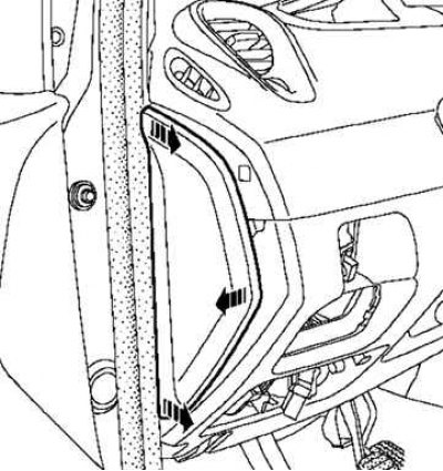
Pic. 6.39. Removal of facing of a forward left rack of a body
Disconnect the left front pillar trim (pic. 6.39).
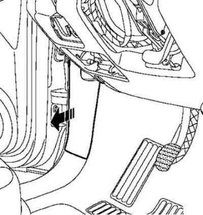
Pic. 6.40. Removing the dashboard side trim
Detach the dashboard side trim (pic. 6.40).
Pic. 6.41. Removing the lower part of the dashboard
Unscrew the fastening bolts and remove the lower part of the dashboard (pic. 6.41).
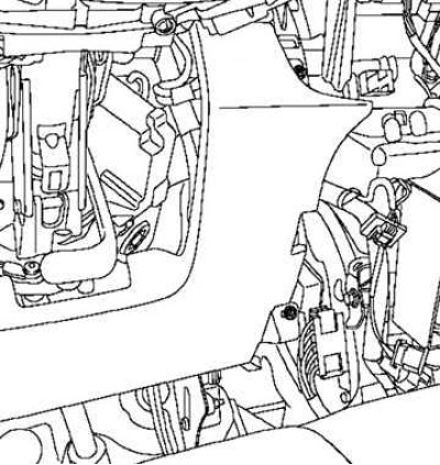
Pic. 6.42. Removing the duct
Remove the duct (pic. 6.42).
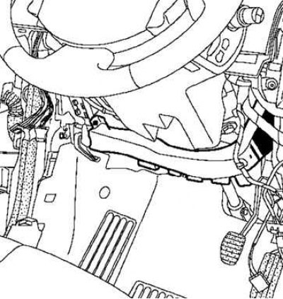
Remove the connecting axis of the node «brake pedal - intermediate link».
Disconnect the accelerator pedal position sensor connector.
Disconnect the brake light switch connector.
Turn the brake light switch a quarter of a turn counterclockwise.
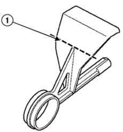
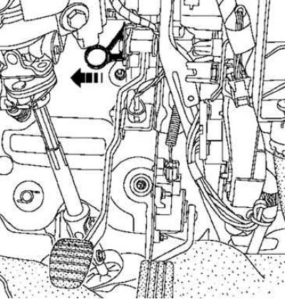
Pic. 6.43. Cutting checks: 1 - cut line
Cut the pin (pic. 6.43).
Insert a check (Fre. 1752) from left to right (when the pedal is not replaced).
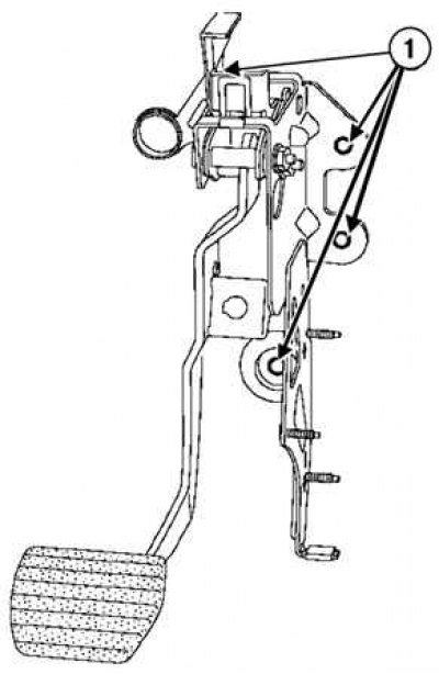
Pic. 6.44. Nuts of fastening of knot of a pedal of a brake: 1 - nuts
Loosen the nuts securing the brake pedal assembly (pic. 6.44).
Remove knot «brake pedal - accelerator pedal».
Loosen the fastening nuts and remove the accelerator pedal.
Installation
Note. The pedal has an unlocking system that works at the moment of a collision. Do not touch the pedal system: the pedal may spontaneously drop to the floor (pic. 6.45).
Note. Do not remove the pin before installing and tightening the pedal assembly fasteners.
Pic. 6.46. check cut line
Cut off the pin in the place shown in Figure 6.46 by the dotted line.
Installation is made in an order, the return to removal.
Torque tighten the brake pedal fork nuts to 21 Nm.
Pic. 6.47. Withdrawal of checks
Remove the pin from the pedal (pic. 6.47).
Note. Check the presence and blocking of the connecting shaft between the push rod of the vacuum brake booster and the brake pedal.
Adjust the position of the brake light switch.
Attach the wires to the battery terminals, starting with the positive terminal.