
Attention! Breaking the toothed drive belt during operation can cause extensive engine damage. Replace the belt at the intervals specified in the Specifications in Chapter Maintenance, or earlier if in doubt about his condition.
Removing
F3R engines
1. Disconnect the ground cable from the battery (contact the head Engine electrical equipment).
Warning: If your car stereo is coded, make sure you know the code before disconnecting the battery.
2. Engage the handbrake, then jack up the front of the vehicle and place it on axle stands. Remove the right front wheel.
3. Turn away screws of fastening and remove the bottom guard of the engine, then remove loose leaves of an arch of the right wheel.
4. Remove the auxiliary drive belt as described in Chapter Maintenance.
5. Set cylinder No. 1 to TDC, also compression, and insert the dowel pin to check the position of the crankshaft as described in Section Top dead center location (TDC) for piston No. 1.
6. Support the engine with a jack, laying a piece of board between them. Raise the jack to bear the weight of the engine on it.
7. Turn away bolts and remove a plastic cover from the right support of the engine, then turn away a fixing nut and bolts and remove the top bracket of a support. Remove the motion limiter/rubber engine mount assembly from the body.
8. Turn away fastenings and remove the top cover of a gear drive belt.
9. Temporarily remove the crankshaft dowel pin and remove the crankshaft pulley bolt. To hold the crankshaft stationary, remove the flywheel/drive plate reinforcement bracket and block the ring gear from rotating using the method shown (refer to illustrations). On manual transmission models, if the engine is in the vehicle, the crankshaft can be locked by shifting into a higher gear and depressing the brake pedal. Do not attempt to use the crankshaft dowel pin for this (refer to section Top dead center location (TDC) for piston No. 1). Remove the crankshaft pulley, then install the pulley bolt onto the end of the crankshaft. Insert the dowel pin into the hole.
10. Turn away bolts of fastening and remove the bottom external cover of a gear drive belt.
11. Turn away bolts of fastening and remove a basic rack from an arm of a forward support of the engine on the block of cylinders. Turn away bolts and remove an arm of a support.
F7R engines
1. Follow the steps described in Section Top dead center location (TDC) for piston No. 1, to set cylinder #1 to TDC on the compression stroke and insert the dowel pin to check the position of the crankshaft.
All engines
1. Loosen the nut and fastening bolt, turn the timing belt tensioner clockwise to reduce belt tension, and tighten the nut again.
2. Remove the belt from the camshaft gear, intermediate shaft and crankshaft gear.
3. Clean gears and tensioners and wipe dry. Do not use excessive amounts of solvent when cleaning the tensioner pulleys, otherwise the bearing lubrication may be contaminated. Also clean the ends of the cylinder head and block.
Note. Renault recommend changing the toothed drive belt every time it is removed. If the belt tension is checked with a special tool, then it will be suitable for further use only if the tension is within the tolerances specified in the Specifications. If the tension is in the lower range of acceptable values, the belt cannot be tightened further, it must be replaced.
Inspection
1. Carefully inspect the toothed drive belt along its entire length, especially at the bases of the teeth. Replace the belt if it is contaminated with oil or grease. Replace any leaking seals. The belt must be replaced if the maximum mileage presented in Chapter Maintenance. Also inspect the gears and tensioner as described in the next Section.
Drive Belt Tension Adjustment - F7R Engines
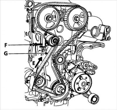
E - Designation of the direction of rotation on the belt
F - Bolt - thread diameter - 6 mm, length - 45 mm
G - Place for checking the tension of the toothed drive belt
Toothed drive belt and timing marks - F3R engines
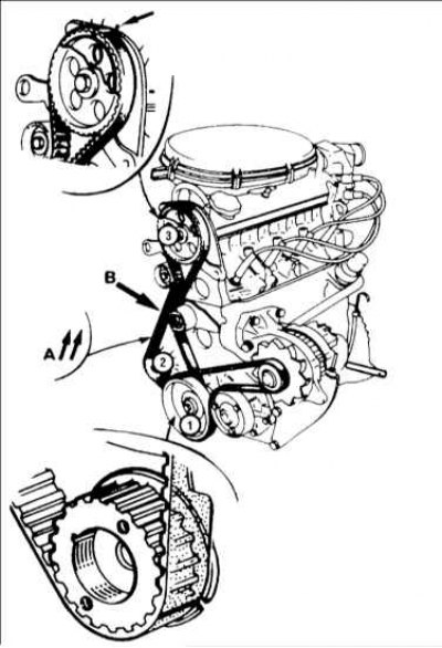
1 - Crankshaft pulley; 2 - Gear wheel of the intermediate shaft; 3 - Camshaft gear; A - The arrows show the direction of rotation of the belt; B - Point for checking the tension of the toothed drive belt
Installation
1. To enable adjustment of the tensioner, screw a 6 mm bolt into the threaded hole in the inner timing belt cover. The bolt will rest against the back of the tensioner pulley and allow you to adjust the belt tension (refer to illustration "Drive Belt Tension Adjustment - F7R Engines" higher).
2. Make sure the No. 1 cylinder piston is at TDC, with the dowel pin in the operating position.
3. Make sure the timing mark on the gear (Oh) camshaft is aligned with the appropriate mark on the inner timing belt cover or on the valve cover.
4. Align the alignment strips on the belt with the alignment marks on the gears. Remember that the arrows for the direction of rotation on the belt must be placed between the intermediate shaft gear and the tensioner pulley. The mark on the crankshaft gear has the form of a notch on the inner edge of the guide. There is no alignment mark on the gear wheel of the intermediate shaft. Install the toothed drive belt first on the countershaft gear, then on the countershaft gear, and finally on the camshaft gear (refer to illustration "Toothed drive belt and timing marks - F3R engines" higher).
5. Make sure all alignment marks are aligned and remove any slack in the toothed drive belt by pressing the bolt screwed into the inner toothed belt cover.
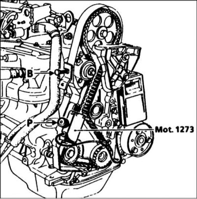
6. Now you need to adjust the belt tension, this can only be done accurately using the Renault Mot tool. 1273 (SEEM C. Tronic 105.6) (refer to accompanying illustration). If this equipment is not available, adjust the belt tension as far as possible using the method described below, and then contact a Renault workshop as soon as possible to check the tension. Do not go on a long trip or drive at high speed until the toothed drive belt tension has been checked.
7. If the adjustment is incorrect, the tensioner will need to be repositioned. The nut of the tension mechanism must be clamped with the force given in the Specifications.
8. Remove the crankshaft locating pin and turn the crankshaft clockwise a minimum of three full turns - never turn the crankshaft counterclockwise.
9. Insert the crankshaft locating pin and make sure that the timing marks of the gear wheel are in place. Recheck the belt tension as described in paragraph 6. If necessary, loosen the tensioner pulley nut and repeat the procedures in paragraph 7.
10. After tensioning the belt, remove the crankshaft locating pin and install the plug. Remove the bolt used to locate the tensioner pulley and securely tighten the tensioner mounting bolt.
F3R engines
1. Establish an arm of a support of the engine and a basic rack on the block of cylinders and tighten bolts of fastening the effort resulted in Specifications.
2. Install the lower outer toothed belt cover and securely tighten the mounting bolts.
3. Establish a crankshaft pulley and tighten a fastening bolt the effort resulted in Specifications. Where necessary, install the reinforced bracket/flywheel/drive plate cover and torque-tighten the mounting bolts to specification.
4. Establish the top external cover of a gear drive belt and reliably tighten bolts of fastening.
5. Attach the travel stop/engine rubber mount assembly to the body, but do not fully tighten the bolts at this stage. Establish the top support bracket and tighten a fixing nut and bolts the effort resulted in Specifications. Make sure the travel stop/rubber cushion assembly is centered on the top bracket, then tighten the mounting bolts to specification. Remove support beam (where available).
6. Install the auxiliary drive belt as described in Chapter Maintenance.
7. Replace the engine undershield and wheel arch liners and install the wheel.
8. Lower the car on the earth and tighten bolts of a wheel the effort resulted in Specifications. Connect the battery.
F7R engines
1. Install all remote components described in Section Top dead center location (TDC) for piston No. 1.