
Note. When installing, use new head bolts, a new head gasket and a new toothed drive belt.
Removing
F3R engines
1. Disconnect the ground cable from the battery (contact the head Engine electrical equipment).
2. Drain the liquid from the cooling system as described in Chapter Maintenance.
3. Remove the toothed drive belt.
4. Remove a casing of the air filter and an inlet air line as it is described in the Head Power and exhaust systems.
5. Remove the inlet pipeline and a final collector as it is described in the Head Power and exhaust systems.
6. Remove the BB of the ignition coil and the BB wire of the spark plugs as described in the Chapter Engine electrical equipment.
7. Disconnect wiring from cylinder head coolant temperature sensor, line pressure sensor, and knock sensor. Release the wire harness from the mounting brackets, noting its direction and location.
8. Turn away two bolts fastening an internal top cover of a gear belt to the block of cylinders. The cover is free and can be removed together with the cylinder head.
9. Loosen the mounting brackets and disconnect the cooling system hoses from the thermostat housing at the left end of the cylinder head.

10. Working in the reverse order of illustration, gradually loosen the cylinder head bolts a half turn at a time until all bolts can be manually loosened and removed. Discard the bolts.
11. Lift the head off the cylinder block. If the dowel pins are loose, remove them and store with the head for safekeeping.
F7R engines
1. Disconnect the ground cable from the battery (contact the head Engine electrical equipment).
2. Drain the liquid from the cooling system.
3. Remove the toothed drive belt.
4. Remove a casing of the air filter and an inlet air line as it is described in the Head Power and exhaust systems.
5. Remove the ignition coil explosives as described in Chapter Engine electrical equipment.
6. Disconnect electrical connectors from the following components:
- a) Camshaft position sensor.
- b) fuel injectors.
- With) Coolant temperature sensor.
- d) Pipeline pressure sensor.
- e) Exhaust gas recirculation valve.
- f) Throttle Potentiometer.
7. Disconnect the vacuum hoses from the throttle body and the pressure sensor in the pipeline, including the vacuum hose of the cooling system, then unscrew the bolts securing the coolant pipe to the left side of the engine.
8. Disconnect the cooling system hoses from the thermostat housing and from the throttle body.
9. Disconnect a cable of a pedal of gas from draft and an arm.
10. Remove the alternator top bracket.
11. From under the inlet pipeline, unscrew the support posts and the tube of the level measurement probe.
12. Release the starter wiring from the fasteners on the cylinder head.
13. Remove the exhaust system support and the fuel line heat shield from the engine.
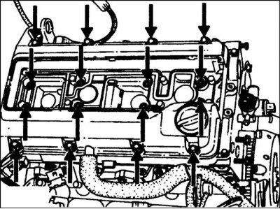
14. Disconnect the crankcase ventilation hose from the valve cover, then unscrew the bolts and remove the cover (refer to accompanying illustration).

15. Working in the reverse order shown in the illustration, sequentially loosen the cylinder head bolts half a turn at a time until all the bolts can be unscrewed by hand and removed. Discard the bolts.
16. With the help of an assistant, lift the head up from the cylinder block. If the dowel pins are loose, remove them and store them together with the head for safekeeping.
Inspection
1. The mating surfaces of the head and cylinder block must be perfectly clean. Use a scraper to remove all traces of gaskets and deposits, and clean the tops of the pistons. Be especially careful with an aluminum cylinder head as the soft metal can be easily damaged. Also, be careful not to get dirt into the oil and water passages - this is especially important for the lubrication chain, as deposits can block the oil supply to the camshaft and crankshaft bearings or rocker arms. Using tape and paper, isolate the water oil passages and bolt holes in the cylinder block. Clean the piston crowns in the same way.
2. Check the block and head for nicks, deep scratches, or other damage. If there are small scratches, they can be carefully removed with a file. More serious damage can be repaired by regrinding, but this work should be entrusted to a specialist.
3. Using a ruler placed on edge, check the curvature of the cylinder head.
4. Clean all bolt holes in the block. Make sure that there is no oil left in them, otherwise there is a possibility that when tightening the bolts, the block may crack under the action of hydraulic pressure.
5. Examine a carving of bolts and a carving in the block of cylinders on presence of damages. If necessary, renew the threads in the block with a tap of the appropriate size and clean the threads on the bolts with a screw-cutting die. It is recommended to replace the bolts after each removal.
Installation
1. Make sure that the mating surfaces of the cylinder block and head are spotlessly clean.
2. Make sure the #1 cylinder piston is still at TDC and that the timing mark (ki) camshaft gear is aligned with the mark on the cover (refer to section Removal, inspection and installation of a toothed drive belt).
3. Make sure the dowel pins are properly seated in the block. Install a new cylinder head gasket, orienting it correctly.
4. Gently lower the head onto the block, sliding it over the pins. Make sure that the inner upper toothed belt cover is correctly positioned on the cylinder block.
5. Lightly grease the new cylinder head bolts. Wait for the excess oil to drain, then insert the bolts with washers and tighten them by hand. Tighten the bolts as described in the appropriate subsection.
F3R engines
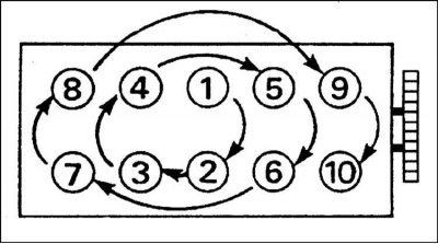
1. In the sequence shown, tighten the cylinder head bolts to the Specifications effort (refer to accompanying illustration). In the initial stages, the preliminary pressing of the gasket is carried out, and the remaining stages are the main compression procedure. When turning the bolts, mark the cylinder head with paint to ensure the correct angle, or purchase a special turning tool. If the bolts are tightened exactly as specified, there is no need to re-tighten them after the first start of the engine.
2. Connect hoses of system of cooling to a casing of the thermostat and fasten them reliably with brackets.
3. Install the bolts securing the inner upper toothed belt cover to the cylinder block and tighten them securely.
4. Make sure the wiring is properly routed and connected to the line pressure sensor, coolant temperature sensor, and knock sensor.
5. Establish VV ignition coils and conducting as it is described in the Head Engine electrical equipment.
6. Establish the inlet pipeline and a final collector as it is described in the Head Power and exhaust systems.
7. Establish a casing of the air filter and an inlet air duct as it is described in the Head Power and exhaust systems.
8. Install a new toothed drive belt as described in Section Removal, inspection and installation of a toothed drive belt.
9. Connect the battery and fill the cooling system as described in Chapter Maintenance.
10. Finally, check the oil level (see Schedule of ongoing maintenance).
F7R engines

1. In the sequence shown in the illustration, tighten the cylinder head bolts as shown in Specifications effort. When turning the bolts, mark the bolt heads and cylinder head with paint to ensure the correct angle, or purchase a special turning tool. After the engine has warmed up to normal operating temperature and then cooled down completely, additional compression will be required. To do this, proceed as follows:
2. Install all affected components in reverse order of removal.
3. Make sure everything is connected and the cooling system is full (contact the head Maintenance), and then start the engine. Let the engine warm up (fan should turn on), then turn it off and let it cool completely.
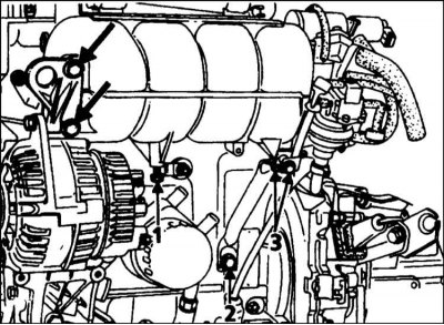
4. From under the inlet piping, loosen the strut bolt and pipeline fixing bolt, and remove the dipstick tube bolt. Loosen also the two bolts holding the brake booster hard vacuum tube and alternator top bracket (refer to accompanying illustration).
5. Remove the ignition coil BB and valve cover to gain access to the cylinder head bolts.
6. When the engine is completely cool, perform the remaining tightening steps in Specifications, at one time in the sequence shown in the illustration of paragraph 1.
7. Install the valve cover and ignition coil BB, then tighten the bolts previously loosened.