
Inspection
1. Apply the handbrake, then jack up the front of the vehicle and place it on axle stands. Where available, remove the lower engine cover.
2. Check the condition of the rubber pad for cracks, hardening, or peeling of the rubber from the metal base; replace the support if there is marked damage or contamination.
3. Make sure the support fasteners are secure; use a torque wrench to check tightening torques.
4. Using a large screwdriver or crowbar, check the bearing for signs of wear by gently prying it to the side. Where possible, have an assistant move the engine/transmission back and forth, or side to side, observing the behavior of the support. If there is excessive play, first check that all fasteners are properly tightened before replacing any worn components as described below.
Front right support
Tightening torques (in Nm) engine/transmission mounts - F3R engines
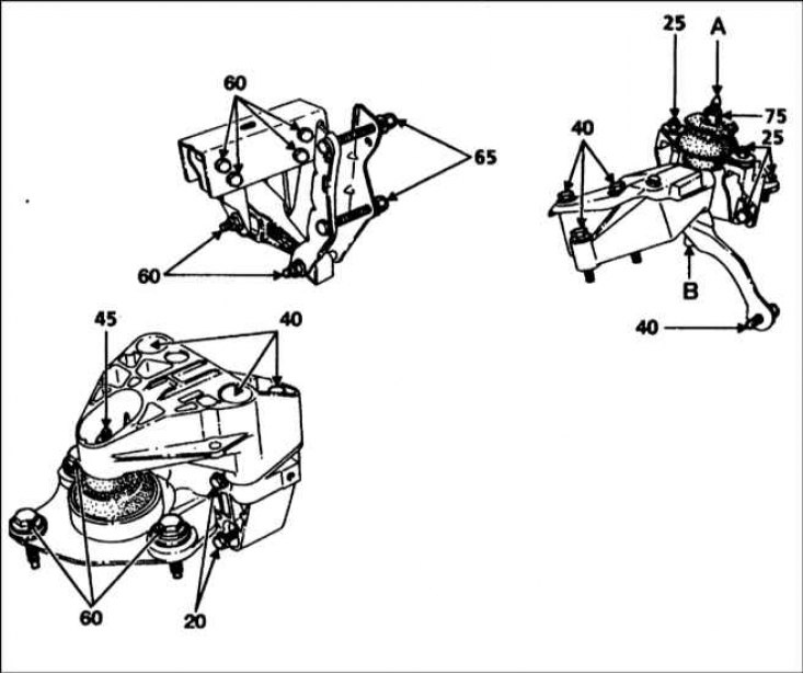
A - Tighten the stud to 60 Nm
B - Tighten the nut to 40 Nm
Tightening torques (in Nm) engine/transmission mounts - F7R engines
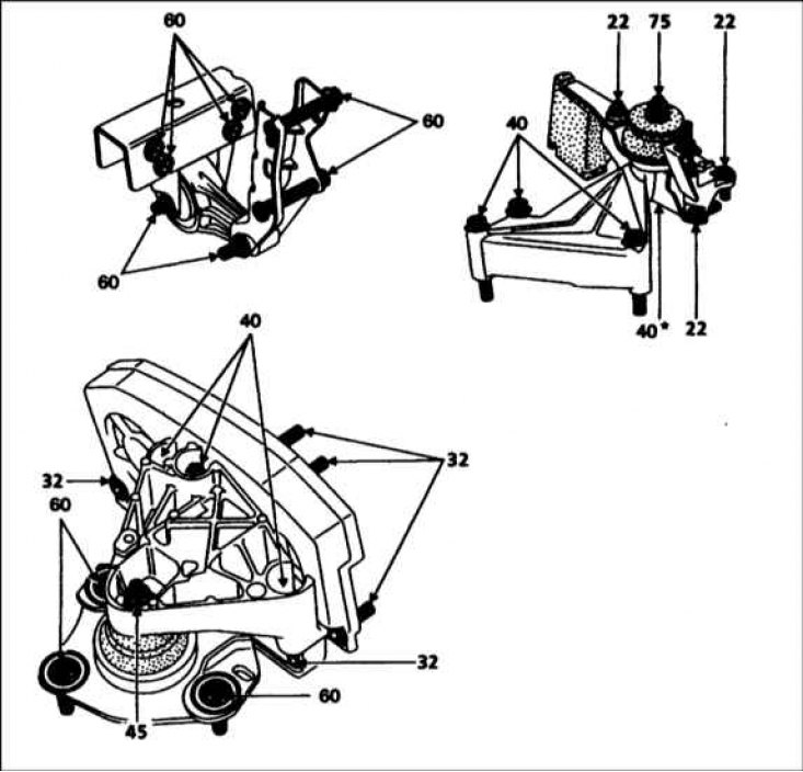
* Refers to the nut under the rubber pad
1. Disconnect the ground cable from the battery (contact the head Engine electrical equipment).
Attention! If the radio in your car is coded, make sure you know the code before disconnecting the battery.
2. Support the engine with a jack, laying a piece of board between them (remove the bottom shield to make it easier to access the sump). Raise the jack to bear the weight of the engine on it.
3. Remove the mounting cover, then remove the three bolts securing the right engine mount upper bracket to the main bracket on the cylinder block. Remove the nut securing the top bracket to the travel stop/rubber cushion assembly on the body and remove the top bracket.
4. Turn away three bolts of fastening and remove assembly of the limiter of the movement/rubber pillow from a body. If necessary, unscrew the main bracket and support leg and remove them from the end of the cylinder block.
5. Carefully inspect all components for damage and signs of wear and replace where necessary.
6. When assembling, install the main bracket and support leg (where removed) on the cylinder block and tighten the mounting bolts given in Specifications effort (refer to the illustrations above).
7. Attach the motion limiter/rubber cushion assembly to the body, but do not fully tighten the mounting bolts.
8. Install the top bracket and tighten the bolts that secure it to the main bracket as shown in Specifications effort. The travel stop/rubber pad assembly must now be centered before the mounting bolts can be tightened. Renault technicians use a special forked grip Mot. 1289-03, which is inserted through the slots into the brackets. If this tool is not available, it can be made from metal strips. Having centered the support, tighten its fasteners given in Specifications effort.
9. Remove the jack from under the engine and attach the ground cable to the battery.
Front left support
1. Place a jack under the transmission with a piece of plank between them. Raise the jack to transfer the weight of the transmission onto it.
2. Turn away the central nut and two bolts of fastening of a rubber pillow and remove a support.
3. If necessary, remove the rubber pad mounting bolts and remove the support bracket from the top of the transmission case.
4. Carefully inspect all components for damage and signs of wear and replace where necessary.
5. Install the stud into the support bracket and tighten it to the Specifications force - refer to the illustrations above.
6. Install the bracket on the transmission, tightening the mounting bolts shown in Specifications effort.
7. Install the rubber cushion on the bracket and tighten the mounting bolts and the central nut given in Specifications effort.
8. Remove the jack from under the transmission.
Rear support
1. If not already done, apply the handbrake, then jack up the front of the vehicle and place it securely on axle stands.
2. Support the pallet with a jack, laying a piece of board between them. Raise the jack to bear the weight of the engine on it.
3. Remove the nut and bolt from each end of the tie-down and remove the tie from under the vehicle. If necessary, remove the mounting nuts and bolts and remove the support bracket and support rod from the engine/transmission.
4. Carefully inspect all components for damage and signs of wear and replace where necessary.
5. When assembling, install the support bracket on the rear of the transmission and tighten the mounting bolts as shown in Specifications force - refer to the illustrations above. Install the support bar.
6. Install the field tie and tighten both bolts to the Specifications effort.
7. Lower the vehicle to the ground.