
Attention! These dowel pins are for the ONLY purpose of checking crankshaft position when performing various engine overhaul procedures. DO NOT use them as locking tools to hold the crankshaft stationary while loosening or tightening the pulley or flywheel/drive plate bolts.
TDC is the highest point in the cylinder that the piston reaches when the crankshaft rotates. Each piston is at TDC at the end of the compression stroke and also at the end of the exhaust stroke. However, to adjust the ignition timing, the TDC at the end of the compression stroke is taken into account. On all engines covered in this manual, cylinder #1 is located at the transmission end of the engine.
1. Disconnect the ground cable from the battery. Apply the handbrake, then jack up the front right side of the vehicle and place it securely on axle stands. Remove the front right wheel.
Attention! If the radio in your car is coded before
disconnect the battery make sure you know the code.
2. Remove the right wheel arch liners to gain access to the crankshaft pulley bolt, then, depending on the engine, proceed as described in the following subsections.
F3R engines
1. Remove a casing of the air filter as it is described in the Head Power systems, release, to access the flywheel/drive plate inspection hole in the clutch housing.
2. Now rotate the crankshaft until the timing mark on the camshaft gear is at the 12 o'clock position and the mark on the flywheel/drive plate is aligned with the TDC mark (0°) on the transmission clutch housing. To see the alignment mark on the camshaft pulley, on most models you will need to unscrew the fasteners, release the brackets (where applicable) and remove the upper outer timing belt cover. Please note that on some models it will be possible to align the mark on the pulley with the pointer in the hole in the timing belt cover.
3. The crankshaft can be turned with a wrench on the pulley bolt. Note that the crankshaft must always rotate clockwise when viewed from the right side of the vehicle.
4. Turn the crankshaft, following the mark on the camshaft gear. When the alignment mark on the pulley is correctly placed, the mark on the flywheel/drive plate must be aligned with the TDC mark (O°) on the transmission. Piston #1 is now set to TDC for compression as well.
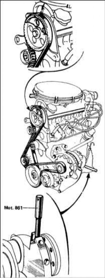
5. Absolutely exact position of the crankshaft can be checked by inserting the locating pin - tool Renault Mot. 861 (early version) or Mot. 1054 (latest version). To do this, unscrew the plug from the front left end of the cylinder block, near the base of the dipstick tube, and insert the dowel pin so that it fits into the groove in the crankshaft. It may be necessary to turn the crankshaft slightly forward or backward (refer to accompanying illustration).
Note. Do not attempt to rotate the motor with the pin installed.
If the engine must be left in this state for a long time, it is recommended that the engine compartment be left to start with a warning.
F7R engines
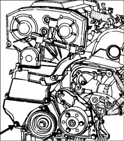
Bolts for fastening the lower outer cover of the toothed drive belt - F7R engines
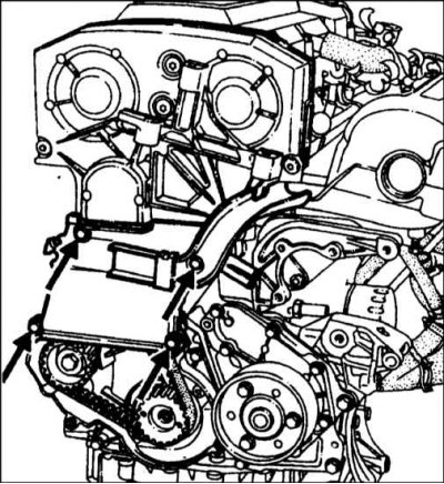
Timing Belt Intermediate Outer Cover Bolts - F7R Engines
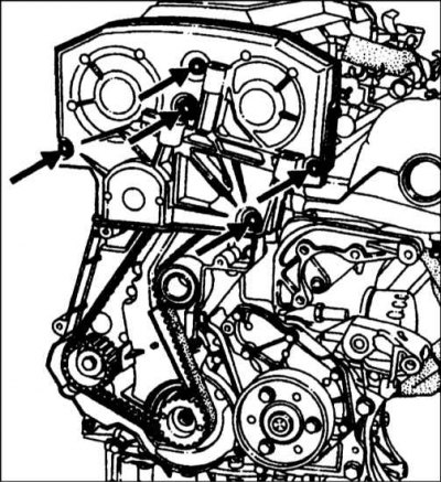
Bolts for fastening the upper outer cover of the toothed drive belt - F7R engines
1. Remove the auxiliary drive belt as described in Chapter Maintenance.
2. Turn away bolts and remove a plastic cover from the right support of the engine, then disconnect a cable of weight of the engine.
3. Remove reinforcing rod (where available) between the domes of the front suspension.
4. Release the power steering hydraulic reservoir and move it to the side.
5. The upper bracket of the right engine mount must be removed so that the upper outer timing belt cover can be removed; therefore, the engine must be supported with a jack or winch.
6. Check that the engine/gearbox assembly is securely supported, then remove the nut securing the top bracket to the motion limiter/rubber cushion assembly - refer to Section Engine/transmission mounts - inspection and replacement.
7. Disconnect the supply and return fuel hoses from the fuel line. Then plug the ends of the hoses.
8. Release fuel hoses from fastening on an intermediate external cover of a driving belt.
9. Ask an assistant to turn on the 4th gear and press the brake pedal.
10. Turn away bolts and remove the bottom, intermediate and top external covers of a gear driving belt (refer to the illustrations above).
11. Temporarily install the crankshaft pulley bolt so that the crankshaft can be rotated.
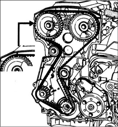
12. Rotate the crankshaft until the timing mark on the camshaft sprocket is at the 12 o'clock position (aligns with the mark on the inner timing belt cover) (refer to accompanying illustration).
13. Turn the crankshaft, following the mark on the camshaft gear. When the timing marks on the pulley are each in place, the number 1 piston will be set to TDC for compression as well.
14. Absolutely exact position of the crankshaft can be checked by inserting the dowel pin - refer to paragraph 5 above and its illustration. You may have to remove the air filter assembly and various tubes and hoses to gain access to the plug.
15. Install all disturbed components in the reverse order of removal. Tighten all nuts and bolts to the specifications Specifications effort where given.