Note: The procedure below applies to 4.7mm copper piping.
The procedure does not apply to hybrid highways (pipeline + hose) and pipelines with a diameter of 6 mm and 8 mm.
The tightening torques given in this procedure apply to removed piping only. In case of using pipelines installed by the manufacturer (pipelines are not replaced with new ones), apply the tightening torques given in the table at the beginning of the chapter.
Caution: To avoid damage to the hydraulic brake system, do not squash or bend the brake pipes when cutting.
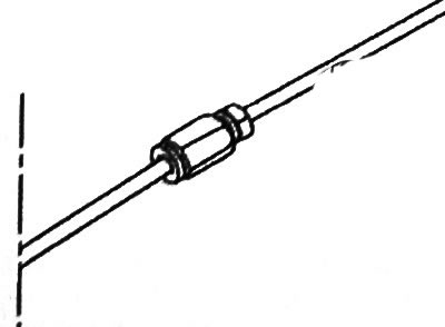
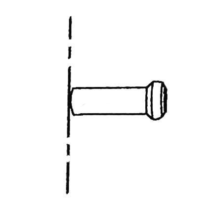
1. Cut a piece of piping to the required length using a suitable pipe cutter.
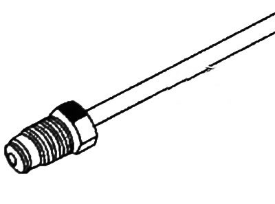
2. Place a nut or threaded sleeve on the pipeline before flaring.
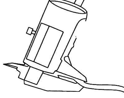
Note: To flare the edges, place the flare tool in a vise.
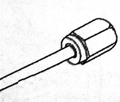
3. Insert the pipeline into the flare tool.
4. Adjust the length of the pipeline.
5. Tighten the end of the flare tool to 40 Nm.
6. Visually check the uniformity of the flare diameter and the centering of the flare relative to the axis of the pipeline.
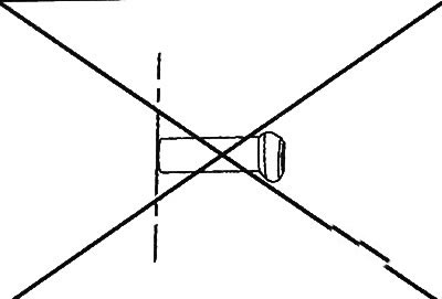
7. Visually verify that the internal opening of the pipeline is not oval.
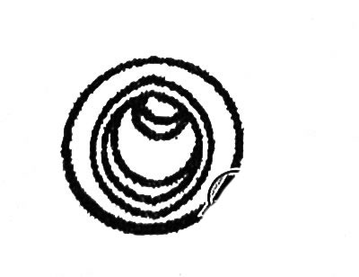
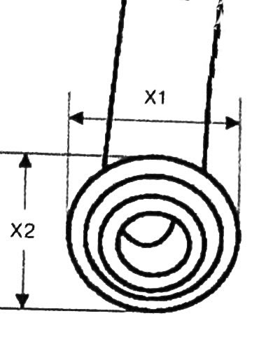
8. Use a caliper to measure the diameter of the end part of the pipeline in mutually perpendicular directions. The end part of the pipeline should not be oval (XI Х2).
Note: When flaring the end of the pipeline, metal inclusions may break off inside the pipeline. It is necessary to blow the pipeline with compressed air in both directions.
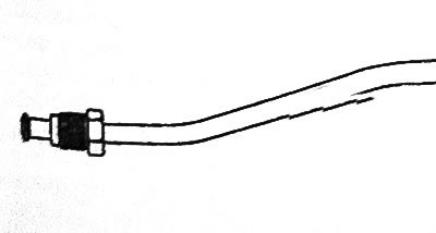
9. Place plugs on nuts or threaded sockets at the ends of the pipeline.
10. Place the original pipeline on a flat base corresponding to the length of the pipeline.
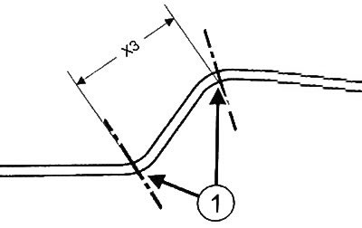
11. Measure the size (HZ) between centers (1) curvature of the original pipeline.
Attention: To avoid weakening the pipeline, either one bend or gradually increase the degree of bending must be performed (reducing the radius of curvature). Do not install on a vehicle a pipe that has been bent and then re-bent to correct the radius of curvature.
Note: During bending of the pipeline, it is necessary to slightly exceed the required rounding angle to compensate for the elasticity of the material.
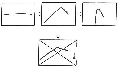
12. Shape the pipeline into the desired shape, bend by bend, respecting the shape of the original pipeline.
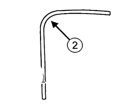
13. Using a vernier caliper, check the ovality of the pipeline along the outer diameter in the central part of the curvature (2). The ovality of the pipeline corresponds to the norm if its value is less than 10% of the flattening of the pipeline. For example, with a nominal pipeline diameter of 4.75 mm, the maximum allowable flattening is 4.3 mm.
Note: When installing the brake line, observe the original position of the gasket as far as possible. Manually adjust the position of the pipelines relative to the clamps of the holders.
Attention: Where the brake line comes in contact with surrounding components, the line may be damaged. To avoid such contact, the piping must be manually adjusted.
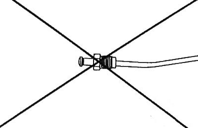
14. Tighten the connecting nut of the pipeline with a torque of 14 Nm.
15.Tighten the brake line connector to 10 Nm.