
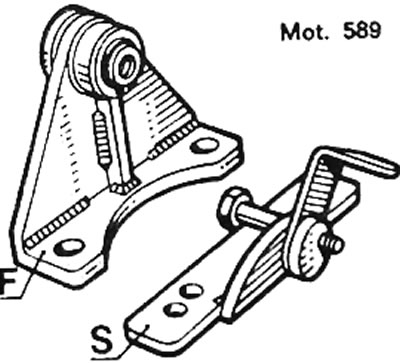
Pic. 2.18. Tool Mot. 589 to keep the chain taut: F - tool 589, used to secure the camshaft sprocket if it is necessary to turn the crankshaft; S - device that keeps the chain taut
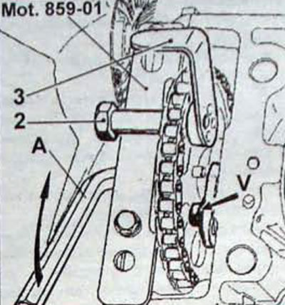
Pic. 2.19. Installation of tool Mot. 589 to keep the chain taut: 2 - bolt; 3 - device; A - hex key; V - camshaft axial stop mounting bolt
To remove the rear cylinder head, you must first remove the engine and gearbox from the vehicle.
Removal
When removing the cylinder head, the following special tools must be used:
- Powertrain support Mot. 1390;
- cylinder head centering bushing remover Mot. 587;
- cylinder liner retainers Mot. 588;
- Camshaft sprocket lock Mot. 589-01;
- wrench with angle gauge for tightening cylinder head bolts Mot 591-02, Mot 591-04;
- Clamp removal pliers Mot. 1202;
- compression bracket Mot. 1209;
- Belt tension checker Mot. 1273;
- centering fork for pendulum suspension travel limiter Mot. 1289-02.
Also, when removing the cylinder head, it is necessary to use anti-tip devices.
- Place the vehicle on a two-post lift equipped with wheel chocks.
- Disconnect the wires from the battery terminals and remove the battery.
- Remove:
protective covers under the engine;
front wheels;
front right and left wheel arches
- Unscrew the right and left side bolts securing the bumper, disconnect the connectors from the fog lights and remove the bumper.
- Remove the radiator trim and radiator grille.
- Drain the coolant from the cooling system by disconnecting the lower hose from the radiator.
- Remove the cooling system element kit.
- Disconnect the exhaust pipe at two points.
- Install a universal support to support the engine.
- Remove:
pendulum suspension bracket and travel stop;
air filter with air intake pipe;
filter bracket.
- Remove the intake manifold cover.
- Using a screwdriver, disconnect the accelerator linkage from the accelerator cable.
- Rotate the throttle valve sector and remove the cable boss and cable from the sector groove.
- Remove the cable along with the sheath.
- Disconnect:
vacuum hoses from the intake manifold;
high-voltage wires from their holders;
connectors from fuel injectors;
connectors from the power ignition module;
wires from the pressure switch and oil temperature sensor;
connectors from the throttle body;
fuel supply and return lines.
- Between the two sections of the cylinder block, remove the 4 wiring harness support bracket bolts and the 5 wiring harness support bolts. From the rear cylinder head side, release the wiring harness support.
- Remove the injection system control unit and move it to the right along with the electrical wiring.
- Unscrew the bolts securing the fuel distribution line and the pressure damper-regulator unit and remove the assembly.
Attention. At each attachment point of the fuel distribution line - damper-regulator assembly there are thermal insulating spacers. Don't forget to remove them when disassembling.
- Remove:
plate connecting the intake manifold to the pendulum suspension bracket,
intake manifold with throttle body;
valve cover.
- Remove the four bolts securing the connecting channel between the cylinder heads
- Remove the bolt securing the rigid tube.
- Disconnect the connecting channel tube between the cylinder heads and the thermostat block tube.
- Remove the exhaust manifold heat shields.
- Remove the heat shield bracket.
- Remove the top bolt securing the generator.
- Remove the oil dipstick guide tube.
- Remove the generator drive belt
- Remove the four upper bolts securing the timing cover to the cylinder head.
- Align the timing marks of the pulleys
- Install tool Mot. 1209 for the balancing chain tensioner (pic. 2.5).
- Remove the balance shaft sprocket bolt, then the camshaft sprocket bolt.
- Remove the balancing chain.
- Remove the balancing mechanism sprockets.
- Slide the shaft to remove the counterweight and key.
- Install tool Mot. 589-01 on the timing cover.
- Install the bolt on the camshaft sprocket (2, fig. 2.19) and adaptation (3). by passing the bolt through the hole in the gear.
- Remove the camshaft sprocket plug.
- Using an internal hexagon, remove the sprocket mounting bolt
- Unscrew the fastening bolt (V) camshaft axial stop, remove the stop from the socket and move the camshaft.
- Using a steel rod, lower the cylinder head alignment sleeve downwards (pic. 2.20).
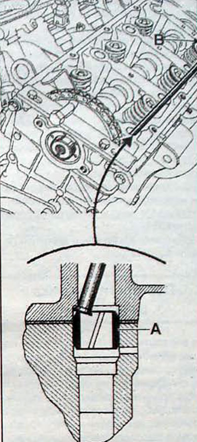
Pic. 2.20. Using a steel rod to lower the centering bushings (A and B)
- Remove the cylinder head. In order not to displace the cylinder liners, the head must be removed by turning it around the remaining guide sleeve.
- Use a syringe to remove the coolant. remaining in the cylinder block.
- Puller Mot. 587 remove the centering bushings from the cylinder block (pic. 2.21).
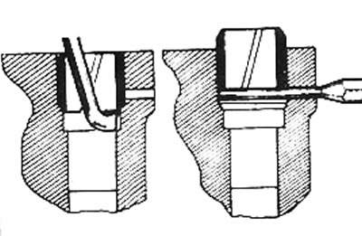
Pic. 2.21. Using steel puller Mot. 587 and a rod with a diameter of 3 mm for removing and installing the centering bushings to the required height
- Remove the cylinder head gasket.
- Using a drift with a diameter of 3 mm, ensure the required protrusion of the centering bushings from the cylinder block.
- Use Decapjoint 77 01 405 952 to clean the mating surfaces of the cylinder head and block.
- Do not allow foreign particles to enter the oil supply and return channels: this can lead to blockage of the oil supply holes to the rocker arm axis and. accordingly, to accelerated wear of the camshaft cams and rocker arms.
- Using a ruler and a set of feeler gauges, check for deformation of the mating plane of the cylinder head. The maximum permissible out-of-flatness is 0.05 mm. Any processing of the mating surface of the cylinder head is not allowed.
- In cases where it is necessary to rotate the crankshaft with the cylinder head removed. for example, when replacing the cylinder-piston group to maintain the valve timing, use the special bracket Mot.589 and bolt it to the front cover (pic. 2.22).
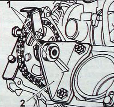
Pic. 2.22. Fixing the camshaft sprocket with tool Mot. 589: 1 - bracket; 2 - device that keeps the chain taut
Note. Avoid any slack in the timing chain. If the valve timing is shifted. you will have to remove the timing cover and reinstall the tensioner.
Installation
Pic. 2.23. Installing gaskets on the front cover
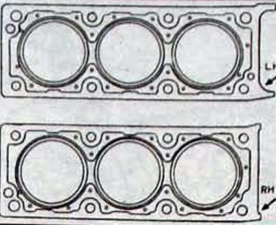
Pic. 2.24. Cylinder head gaskets
- Installation is carried out in sequence. reverse to withdrawal.
- Apply Autojoint AJ66 (7701 422 751) on the mating surfaces of the timing cover.
- Insert pins with a diameter of 3 mm into each of the holes for the centering bushings and press the bushings all the way into the pins to prevent the bushings from moving during installation of the cylinder head.
- Remove the bracket for tool Mot. 589.
- Install the gaskets on the front cover.
- Install a new cylinder head gasket (without using sealant). The gaskets for the left and right sides of the engine are different. When installing the gasket, check that the bolt holes and lubrication holes are aligned.
- Loosen the camshaft longitudinal movement clamp bolt and remove the clamp from the camshaft groove.
- Smoothly move the camshaft
- Install the cylinder head and screw in the timing cover bolts and tighten them by hand.
- Install the camshaft and connect it to the sprocket, installing it on the key, but not completely tightening it.
- Make sure the stop is far enough away from the camshaft flange (pic. 2.25). Lightly tighten the camshaft sprocket bolt.
- Remove tool Mot. 589-01.
- Move the camshaft towards the sprocket until it stops and tighten the sprocket mounting bolt to the required torque.
- Remove the 3 mm diameter pins from under the centering bushings.
- Install the valve drive with a balancing mechanism.
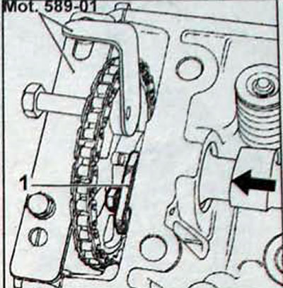
Pic. 2.25. Location of tool Mot 589-01, stop (1) and the direction of movement of the camshaft
Attention. The balancing mechanism shaft key may fall out, so you should cover the timing gear housing with a rag.
- Tighten the cylinder head bolts in several stages in the sequence shown in Figure 2.26.
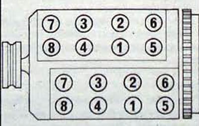
Pic. 2.26. Sequence of tightening the cylinder head bolts
Stage 1 - tighten all bolts to 60 Nm.
Stage 2 - loosen all bolts.
Stage 3 - tighten all bolts to 40 Nm.
Stage 4 - tighten all bolts to an angle of 180°.
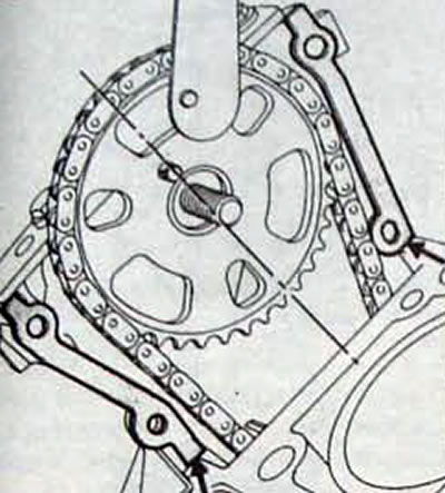
- No further tightening of the bolts is required. Install the sprocket (A. fig. 2.27) along with the chain, then the sprocket (IN), aligning the marks (1) And (2).
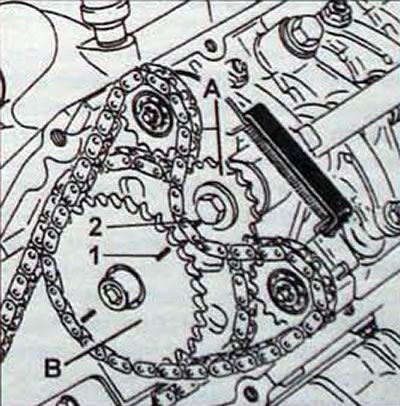
Pic. 2.27. Installation of camshaft and balancing shaft sprockets: 1 - installation mark of the camshaft sprocket; 2 - alignment mark of the balancing shaft sprocket; A - balancing shaft sprocket; B - camshaft sprocket
- Apply a drop of Loctite FRENETANCH to the threads of the balancing sprocket bolts and tighten them to the required torque.
- Release the chain tensioner of the balancing mechanism by removing tool Mot. 1209.
- Install the pendulum suspension bracket, centering fork Mot. 1289-02 to center the suspension travel stop and remove the support from under the engine.
- Tighten the bolts and nut securing the pendulum suspension and travel stop to the required torque.
- Place the engine in its original position, then remove the centering fork Mot. 1289-02.
- Using tool Mot. 1273 adjust the tension of the generator drive belt.
- Fill the cooling system with coolant and remove air from it.
- Adjust the accelerator cable.
- Tighten the spring-loaded bolts securing the exhaust pipe flanges until they stop.
- Install engine attachments.