
If there is no power supply to the valve
Air channel closed, plunger (4. fig. 2.3) shifted in the direction of the winding (3) spring (5). core (2) pressed against the valve plunger by a small spring (1).
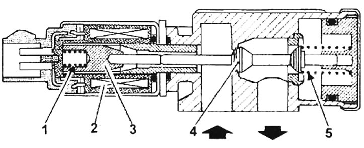
Pic. 2.3. Idle air control valve: 1 - spring; 2 - core; 3 - winding; 4 - plunger; 5 - spring
Ignition on, engine stopped
The injection system control unit controls the valve via channel 54 (intermittent short circuit to «mass»)
The valve receives a signal at 95% open, but remains closed because it is not receiving +12 V power through the fuel pump relay (the relay is controlled a few moments after turning on the ignition and turns on only when the injection system control unit receives information about TDC).
The engine is idling
The magnetic field created by the winding moves the core, which in turn pushes the plunger.
The injection control unit maintains a cyclic opening mode in accordance with the required air supply to ensure the required idle speed (depending on engine operating conditions).