
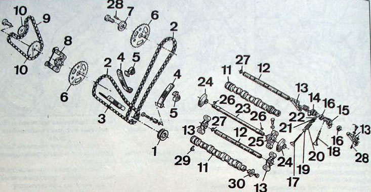
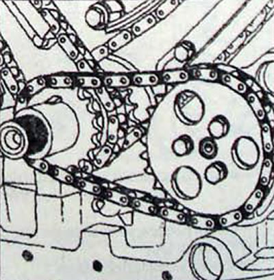
Pic. 2.9. Gas distribution mechanism:1 - crankshaft sprocket; 2 - camshaft drive chains; 3 - shoe; 4 - chain tensioner shoe; 5 - hydromechanical chain tensioner; 6 - camshaft sprocket; 7 - eccentric; 8 - automatic device for tensioning the balancing shaft drive chain; 9 - balancing shaft drive chain; 10 - asterisk; 11 - camshafts; 12 - rocker axis; 13 - rocker arm axis support; 14 - exhaust valve rocker arm; 15 - intake valve rocker arm; 16 - spacer sleeve; 17 - exhaust valve; 18 - inlet valve; 19 - lower spring plate; 20 - valve spring. 21 - upper spring plate; 22 - crackers; 23 - balancing shaft; 24 - balancers; 25 - support for the balancing shaft; 26 - key; 27 - retaining ring; 28 - pin «Mecanindus»; 29 - distributor drive bushing
Attention
- If one part needs to be replaced, all timing drive parts must be replaced: chains, sprockets, shoes and tensioners.
- This operation requires removing the engine along with the gearbox.
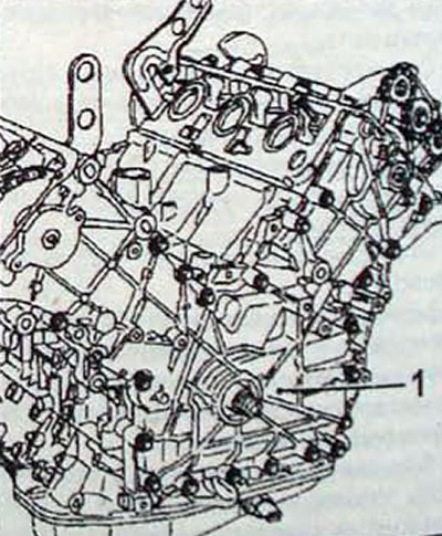
Pic. 2.10. Cover location (1) the drive of the gas distribution mechanism
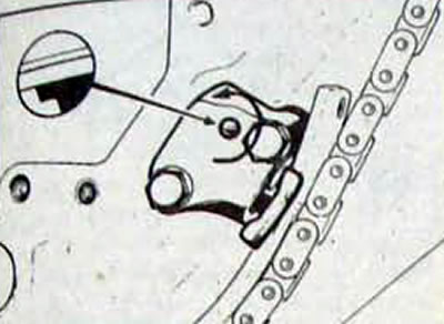
Pic. 2.11. To loosen the chain tension, turn the lock counterclockwise
Removal
- Remove the engine and transmission from the car.
- Remove the engine mount bracket mounting panel.
- Remove the thermostat housing.
- Remove the accessory drive belt pulley and remove the oil seal.
- Rotate the crankshaft so that the accessory drive belt pulley key is vertical at the top.
- Remove the front and rear cylinder head covers.
- Remove the timing cover
- Remove the oil pump sprocket bolts and simultaneously remove the two sprockets, chain, crankshaft spacer and key.
- Loosen the automatic chain tensioner as much as possible and use tool Mot 1209 to secure it in this position.
- Remove the bolts securing the camshaft sprocket of the front cylinder head and the balancing shaft sprocket.
- Loosen the camshaft drive chain tensioners as much as possible and fix them in this position by turning the latches counterclockwise with a screwdriver.
- Do not remove stopper 1 (pic. 2.12) chain tensioner Position of this stopper (active or passive) determined by the action of the spring (2), which pushes the ball (3) into the locking channel.
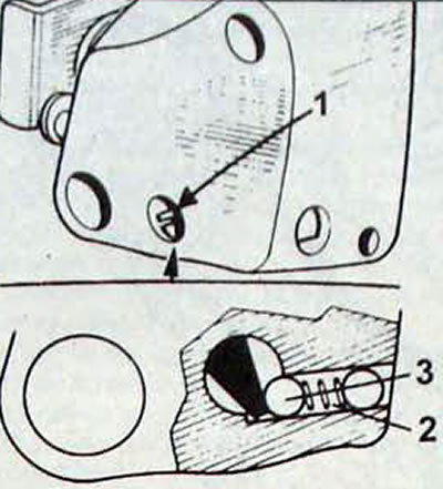
Pic. 2.12. Chain tensioner stopper: 1 - stopper; 2 - spring; 3 - ball
- If the stopper was removed accidentally, it is necessary to replace the entire tensioner, since during installation you cannot be sure of the correct location of the stopper in relation to the pressure ball (due to the danger of placing the locking channel on the spring coils).
- Remove the chain tensioners, being careful not to damage the filters located behind the tensioners
- Remove the rear cylinder head camshaft sprocket bolt.
- Remove the shoes from the stretched target branch
- At the same time, remove the chain and sprocket from the rear cylinder head camshaft.
- At the same time, remove the chain and 2 sprockets from the front cylinder head camshaft, being careful not to lose the key (pic. 2.13).
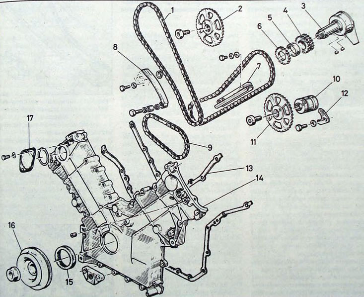
Pic. 2.13. Timing mechanism drive: 1 - Chain; 2 - camshaft sprocket; 3 - crankshaft; 4 - crankshaft sprocket; 5 - spacer sleeve; 6 - oil pump drive sprocket; 7 - chain guide shoe; 8 - chain damper; 9 - oil pump drive chain; 10 - camshaft; 11 - camshaft sprocket; 12 - camshaft fixing plate; 13 - cover gasket; 14 - front cover; 15 - front sealing ring of the crankshaft; 16 - crankshaft pulley; 17 - protective plate
Installation
- Rotate the engine crankshaft so that the keyway on the crankshaft faces the front section of the cylinder block.
- Install a new filter and chain tensioner on the front section of the cylinders.
- Install key 1 sprocket on the crankshaft.
- Install the shoe and secure with the bolt, after lubricating its threads with Loctite Frenetanche. Install the front cylinder head camshaft sprocket into the chain so that the timing mark on the front side of the sprocket is between the two timing marks, as shown in Figure 2.14.
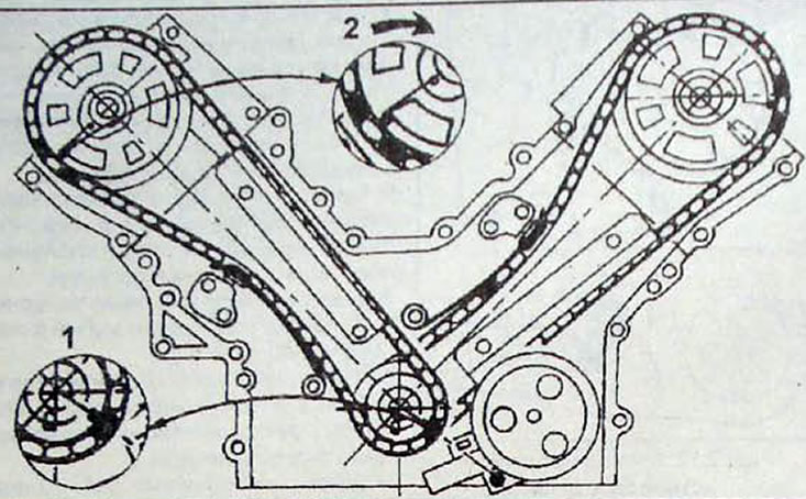
Pic. 2.14. Front cylinder head camshaft position: 1 - crankshaft key, turned towards the front section of the block; 2- mark on the camshaft sprocket, located between the two marks of the cylinder chain
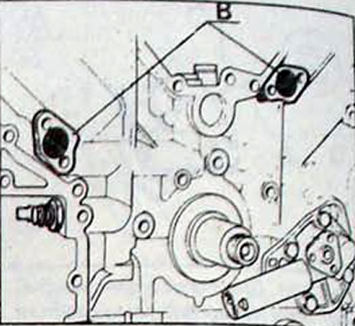
Pic. 2.15. Location of oil filters (IN) chain tensioner
Pic. 2.16. Rear cylinder head camshaft position: 1 - crankshaft key turned vertically downwards; 2 - mark on the camshaft sprocket, located between two chain marks
Pic. 2.17. Oil pump drive chain and sprockets
- While maintaining the chain and sprocket in this position, install the bottom of the chain onto the crankshaft sprocket and align the single mark on the chain link with the timing mark on the front side of the sprocket.
- Install the sprocket onto the front cylinder head camshaft.
- Install the shoe and secure with the bolt, after lubricating its threads with Loctite Frenetanche.
- Rotate the engine crankshaft so that the keyway on the crankshaft is vertically at the bottom.
- Install a new filter and chain tensioner to the rear section of the cylinder block.
- Install the shoe and secure with the bolt. having previously lubricated its threads with Loctite FrenWanche blocking agent.
- Install the rear camshaft sprocket into the chain so that the timing mark is between the marks on the chain links. Support the chain and sprocket in this position and install the chain on the crankshaft sprocket so that the mark on the chain link aligns with the timing mark on the crankshaft sprocket.
- Install the sprocket onto the camshaft of the rear cylinder head, ensuring that the protrusion on the sprocket fits into the groove of the camshaft.
- Install the shoe and secure with the bolt, after lubricating its threads with Loctite Frenetanche.
- Screw in the camshaft sprocket mounting bolt for the rear cylinder head and tighten it to the required torque.
- Release the chain tensioners.
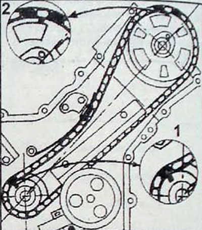
- Install the balancing shaft sprocket together with the chain, ensuring that the mark on the balancing shaft sprocket is aligned with the mark on the camshaft sprocket.
- Apply Loctite Frenetanche to the sprocket bolt threads and install the bolt.
- Remove the device blocking the automatic chain tensioner and check the chain tension.
- Install the spacer bushing, key and oil pump drive sprocket onto the crankshaft.
- Install the oil pump drive chain and sprocket and secure with bolts, having previously lubricated the bolt threads with Loctite Frenetanche locking agent
- Apply a layer of sealant to the mating surface of the timing cover.
- Install the timing cover and secure with bolts, after lubricating the threads of the smaller bolts with Loctite Frenetanche
- Apply Loctite Frenetanche to the threads of the cylinder head cover bolts.
- Apply a thin layer of sealant to the mating surface of the cylinder head cover, install the cover and secure it with bolts
- Install the thermostatic housing.
- Using tool Mot 658, install the oil seal in the timing cover.
- Install the accessory drive belt pulley and secure it with a nut.
- Install the engine mount bracket panel.
- Install the engine and gearbox into the car.