
English Русский
Български
Беларускі
Український
Српски
Hrvatski
Română
Polski
Slovenský
Magyar
Bookmark Contacts Articles Sitemap
Company vehicles Peugeot Company vehicles Opel Company vehicles Skoda Company vehicles Land Rover Company vehicles Mitsubishi Company vehicles Volkswagen Company vehicles Honda
RenaultBook.ru


Duster   Fluence   Kangoo   Laguna   Logan   Megane   Sandero   Scenic   Symbol   Clio   Other
Symbol 1 (1999-2008, petrol) Symbol 2 (2008-2013, petrol)

Vacuum brake booster — removal and installation (Renault Symbol 2)

  • Main
  • Symbol
  • Symbol 2 (2008-2013, petrol)
  • Chassis, running gear
  • Brake system
  • Vacuum brake booster — removal and installation
0
Contents: Removal 🠛 Installation 🠛 Checking the amplifier 🠛 Checking the seal 🠛
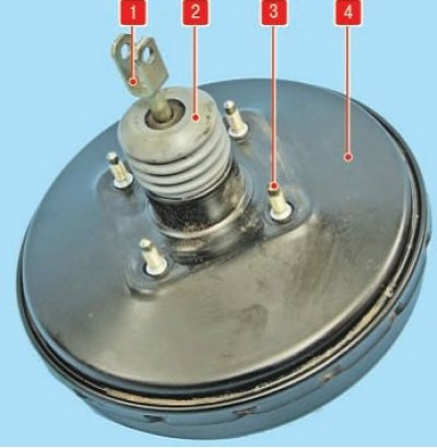
Vacuum booster: 1 - pusher; 2 - protective cover with filter; 3 - vacuum booster mounting stud; 4 -…

Vacuum booster: 1 - pusher; 2 - protective cover with filter; 3 - vacuum booster mounting stud; 4 - amplifier body


Tightening torques:
  • Brake master cylinder nuts - 18 Nm
  • Vacuum booster nuts - 23 Nm

The brake booster is not repairable. During operation, the booster air filter and check valve are replaced.

Removal


1. Disconnect and remove the battery.

2. Remove the brake master cylinder.

3. Unscrew the four bolts and one nut securing the battery protection, remove the protection.

4. Unscrew the two expansion tank mounting nuts, remove the tank and secure it to the side.

5. Disconnect the vacuum hose from the vacuum booster.

6. In the salon:
  • remove the clip (A) securing the brake pedal pin to the booster rod;
  • unscrew the four nuts securing the amplifier.
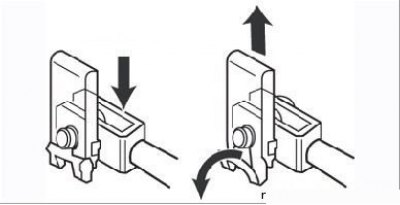
Figure 7.21. Brake pedal connection unit with brake booster pushrod fork (the arrow shows the fork…

Figure 7.21. Brake pedal connection unit with brake booster pushrod fork (the arrow shows the fork axis)


7. Remove the amplifier from the engine compartment.
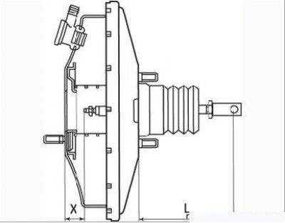
Figure 7.22. Before installation, check the length of the rod L (104.8 mm) and the pusher X (22.3…

Figure 7.22. Before installation, check the length of the rod L (104.8 mm) and the pusher X (22.3 mm).

  • check the adjustment dimensions of the amplifier (Figure 7.22) and restore them if necessary.

Installation


Installation is carried out in the reverse order of removal.

Remove air from the brake system drive.

Checking the amplifier


Without starting the engine, press the brake pedal several times to remove the vacuum in the booster chamber and, holding the pedal pressed all the way down, start the engine. Simultaneously with the engine running, the brake pedal should "fall" slightly, this means that the vacuum brake booster is working properly.

If the pedal does not "fall through", you should check the booster air filter. To do this, remove the rubber cover in the rear of the booster in the passenger compartment near the brake pedal and slide the cover along the rod.
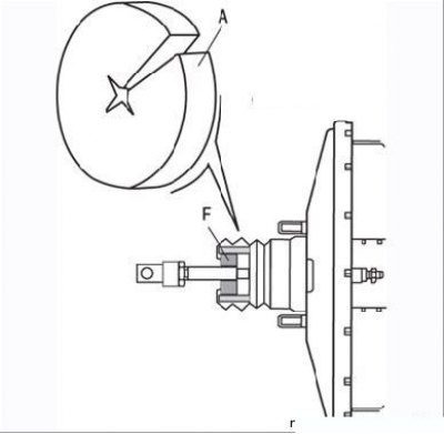
Figure 7.23. Replacing the brake booster air filter: A – air filter cut area; F – air filter…

Figure 7.23. Replacing the brake booster air filter: A – air filter cut area; F – air filter installation location


To replace the filter, it is not necessary to remove the vacuum booster: under the control pedal support, use a screwdriver or a metal hook to remove the old filter (F).

In the new filter (A), make a radial cut and put the filter on the vacuum booster rod. Put the filter in place and straighten it.

Using a screwdriver, as shown in Figure 7.23, remove the old air filter. Then, having made a cut in the new filter, install it in its proper place, making sure that it covers all the holes. Install the rubber cover and check the operation of the amplifier again.
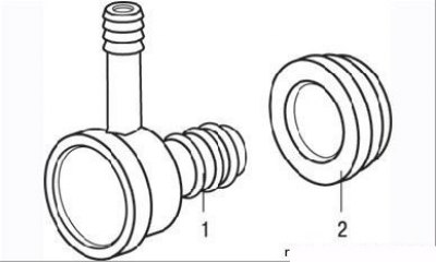
Figure 7.24. Brake booster check valve: 1 – valve; 2 – rubber seal

Figure 7.24. Brake booster check valve: 1 – valve; 2 – rubber seal


If the result is unsatisfactory, try replacing the booster check valve. To do this, disconnect the vacuum hose from the vacuum booster. Pull out the check valve (Figure 7.24), rotating it to remove it from the rubber seal.

Blow the valve, air should flow only in one direction - from the booster side. If the valve does not blow or blows in both directions, replace it. Check the condition of the rubber seal. Assemble the unit, connect the vacuum hose and check the operation of the booster.


If the amplifier still does not work, replace it, as the company does not supply a repair kit of parts.

Checking the seal


Special devices:
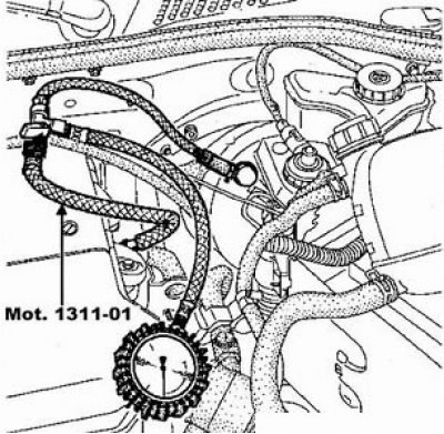
  • Pressure gauge and adapters - Mot. 1311-01

1. Check the condition of the seal between the master cylinder and the vacuum booster.

If there are any signs of leakage, replace the seal, see. "Master brake cylinder".
(Original article is on the portal RENAULTBOOK)

If there are any signs of leakage, replace the seal, see. «Master brake cylinder».


2. Install the pressure gauge Mot. 1311-01 between the vacuum booster and the intake manifold:
  • a) Remove the vacuum hose.
  • b) Place a technological piece of hose on the check valve nipple (1).
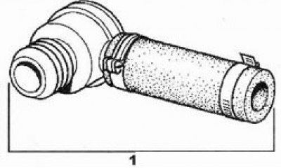
b) Place a technological piece of hose on the check valve nipple (1).

  • c) Secure the adapter (B) from the Mot. 1311-01 kit with clamps (2).
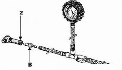
c) Secure the adapter (B) from the Mot. 1311-01 kit with clamps (2).

  • d) Connect the pressure gauge hose to the intake manifold fitting. The pressure gauge tap should be located on the intake manifold side. Open the tap.

3. Run the engine at idle speed for one minute.


4. Close the pressure gauge valve and turn off the engine.

5. The pressure gauge should register a vacuum of about 613 mbar. If the vacuum decreases at a rate greater than 33 mbar in 15 seconds, then there are leaks in the system (either in the check valve or in the amplifier itself). If the amplifier is leaking, replace it as an assembly.
This article is available on: russian, bulgarian, belarusian, ukrainian, serbian, croatian, romanian, polish, slovak, hungarian
Article has been reviewed by editor: Kupriyanov Sergey
Share with friends:
Previous
Symbol 2: Brake system
Next

Master Brake Cylinder — Removal and Installation
Rear brake cylinder — removal and installation
Rear brake pads — removal and installation
Brake drum — removal and installation
Brake pressure regulator
Brake hoses — removal and installation
Removal and installation the parking brake lever
Adjusting the handbrake
Replacing the handbrake cable
Brake light switch
Other articles on other Renault models

➽ Vacuum brake booster Renault Duster 1 (2009-2017)
➽ Vacuum brake booster Renault Fluence 1 (2009-2020, petrol)
➽ Vacuum brake booster Renault Kangoo 1 (1997-2007)
➽ Installing a vacuum brake booster Renault Laguna 2 (2001-2007)
➽ Brake booster vacuum — check Renault Scenic 1 (1996-2003)
Link to this article in different formats
Reviews and comments of visitors
No comments yet


Add two numbers 29 + 50


Symbol 2 (2008-2013, petrol) 
  • General information
  • User manual
  • Maintenance
  • Power unit
  • Engine repair
  • Cooling system
  • Fuel system
  • Exhaust system
  • Ignition system
  • Transmission
  • Clutch
  • Mechanical gearbox
  • Automatic gearbox
  • Drive shafts
  • Chassis, running gear
  • Front suspension
  • Rear suspension
  • Steering
  • Brake system
  • Body and interior
  • Exterior (external elements)
  • Interior (internal elements)
  • Doors, locks and windows
  • Heating and ventilation
  • Electrical equipment
  • Equipment and devices
  • Headlights and lighting
  • Power devices
  • Electrical circuits
Symbol 1 (1999-2008, petrol) 
  • General information
  • User manual
  • Car care
  • Maintenance
  • Power unit
  • Engine repair
  • Cooling and lubrication system
  • Supply system
  • Exhaust system
  • Ignition system
  • Transmission
  • Clutch
  • Mechanical gearbox
  • Automatic gearbox
  • Drive shafts
  • Chassis, running gear
  • Car suspension
  • Steering
  • Brake system
  • Body and interior
  • Exterior (external elements)
  • Interior (internal elements)
  • Doors, locks and windows
  • Restoration and repair
  • Electrical equipment
  • Equipment and devices
  • Headlights and lighting
  • Power devices
  • Heating and ventilation
  • Electrical circuits
RenaultBook.ru © 2018–2026 | Mobile version | News and articles | Sitemap: EN BG BY UA RS HR RO PL SK HU | Administration | Site search | Bookmark
Duster 1 (2009-2017) | Fluence 1 (2009-2020, petrol) | Kangoo 1 (1997-2007) | Laguna 2 (2001-2007) | Logan 1 (2004-2012, petrol) | Logan 2 (2012-2020) | Megane 1 (1995-2002) | Megan 2 (2002-2009, petrol) | Sandero 1 (2007-2012, petrol) | Scenic 1 (1996-2003) | Symbol 1 (1999-2008, petrol) | Symbol 2 (2008-2013, petrol) | Renault 19 (1988-1996) | Espace I and II (1984-1996) | Espace III (1996-2002) | Clio 1 (1990-1998) |
We want your visit to be comfortable 😌 and use cookies 🍪 to do so.