



Brakes work most effectively when there is maximum friction between the tires and the road surface. When braking, the tire begins to slip on the road surface and the peripheral speed of the wheel becomes less than the speed of the car.
Tire slip is zero when the wheel rotates freely and 100% when the wheel is locked. Maximum braking efficiency is achieved with a slip coefficient of 15%.
This value of the slip coefficient ensures reliable control and the best stability of the vehicle.
The purpose of the anti-lock braking system is to instantly limit the pressure in the brakes to obtain an optimal coefficient of wheel slip. ABS instantly affects the brake of each wheel, reacting to changes in the properties of the road surface or the load on the wheel.
The ABS system consists of an electronic control unit (ECU), a hydraulic unit with hydraulic electromagnetic valves, an electrically driven return pump and rotation speed sensors installed on each wheel.
The electromagnetic valves are controlled by signals coming from the ECU, which in turn is controlled by signals coming from four wheel speed sensors. The magnetic wheel speed sensors receive signals from a toothed ring mounted on the wheel hub. By comparing these signals, the ECU can calculate the speed of the vehicle's wheels. If the speed of any wheel deviates from the speed of the vehicle, the system processes the signals received and predicts the moment when the slowing wheel will lock.
If the system detects that a wheel is locked, it commands the appropriate valve to isolate the fluid supply to that wheel's brake cylinder from the master cylinder.
If the wheel speed continues to decrease relative to the other wheels, the ABS system forces brake fluid back into the master cylinder, reducing braking. If all four wheels slow equally, the return pump stops and all solenoids open again, allowing the master cylinder to apply pressure to the wheel cylinders as normal. This cycle can repeat up to ten times per second.
The activation of the electromagnetic valves and the return pump creates pulsations in the brake system, which are transmitted to the brake pedal, thereby indicating to the driver that the ABS is engaged.
The solenoid valves in the front circuit act on the brake calipers of the front wheels independently, while the solenoid valve for the rear wheels acts on both wheels simultaneously. Since the braking system is diagonally divided, a separate mechanical plunger valve in the hydraulic unit divides the hydraulic output of the rear solenoid valve into two separate circuits. To prevent false signals from affecting the system, an integrated safety circuit monitors all signals sent to the ECU. If a false signal is received or the voltage in the network is insufficient, the system is automatically switched off and a warning signal for the ABS system to be switched off lights up on the panel. At the same time, the normal operation of the braking system is maintained.
However, when driving on slippery roads, you need to be extremely careful, since the distribution function of the system will be impaired (function of equalizing pressure in front and rear brakes) and there will be a risk of the car skidding when braking.
If a malfunction occurs in the system, you should present the car to specialists for diagnostics and repair.
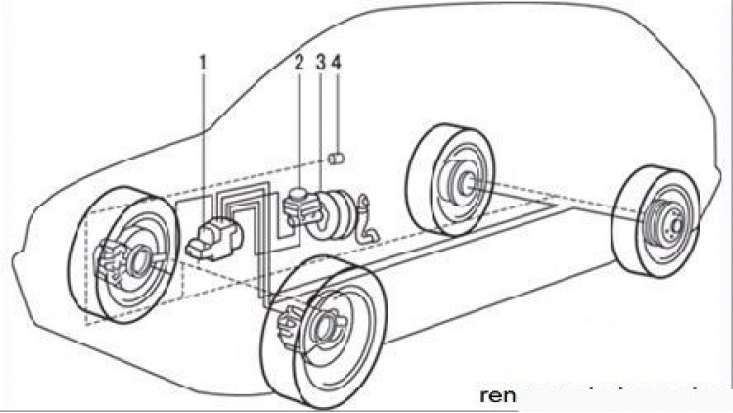
Figure 7.34. Location of Bosch ABS units and components on the vehicle: 1 – hydraulic unit; 2 – main brake cylinder; 3 – brake booster; 4 – ABS off indicator lamp in the instrument cluster