



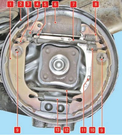
Rear brake mechanism: 1 - front brake shoe; 2 - brake mechanism shield; 3 - gap adjustment mechanism earring; 4 - upper tension spring; 5 - clearance adjuster; b - working cylinder; 7 - spacer bar; 8 - rear brake shoe; 9 - support stand; 10 - tension spring of the spacer bar; 11 - parking brake release lever; 12 - Parking brake drive cable; 13 - lower tension spring
Attention! Replacement of brake pads is carried out only in sets of four pads per rear axle to avoid uneven braking of the wheels and the possibility of skidding of the car.
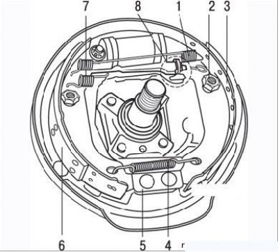
Figure 7.16. Drum brake mechanism parts: 1 – upper tension spring; 2 – clamping device; 3 – brake shoe; 4 – lower tension spring; 5 – support plate; 6 – brake shoe release; 7 – return spring of the adjusting rack; 8 – automatic clearance adjustment device
Removal
- remove the brake drum as described above;
- carefully remove dirt and dust from the drum, shoes and brake shield with the parts installed on it;
- press the cap of the clamping device "away from you" with pliers, turn it 90° and remove the cap, spring and stand. Do the same on the other shoe;
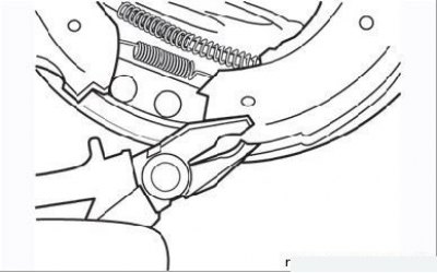
Figure 7.17. Disconnecting the shoe from the support plate
- using pliers, separate the lower ends of the pads from the support plate one by one (Figure 7.17) and remove the lower spring from the brake pads;
- move the upper pad stops away from the brake cylinder, being careful not to damage the rubber boots;
- disconnect the parking brake cable from the operating lever;
- remove both brake pads from the brake shield together with the springs and spacer strut;
Caution! Do not press the brake pedal before installing the pads and drums.
- tighten the brake cylinder pistons with a strong rubber band;
- place the removed unit on the workbench, mark and remember the location of the mating parts;
- release the parking brake release lever locking lug from the pressure shoe;
- disconnect the adjusting strut bolt spring from the pressure shoe;
- disconnect the upper tension spring;
- disconnect the pressure shoe and tension spring from the pressure shoe assembly with the adjustment stand;
- unhook the return spring of the adjusting stand from the release shoe and separate them;
- measure the thickness of each pad in several places and, having compared the results of the measurements with the minimum thickness of the pad, decide on replacement or further use of the pad. Oiling of the friction surface of the pad clearly indicates the need for its replacement. At the same time, it is necessary to find out and eliminate the cause of oiling.
Replacement procedure:
- remove the parking brake operating lever from the old release shoe and install it on the new shoe, securing it with the new retainer that is included with the shoe kit;
- remove the bolt from the adjusting stand and inspect this unit for wear and damage, paying particular attention to the adjusting bolt and wing nut. Replace any faulty parts;
Attention! When replacing the pads, it is necessary to replace all tension springs, regardless of their condition.
Attention! The adjustment posts of the right and left wheels are not interchangeable. The adjustment bolt of the right post has a right-hand thread and is painted. The left bolt has a left-hand thread and a groove on the head. The right adjustment post is marked with the letter "D", the left one - with the letter "G".
- make sure the parts are installed correctly, apply molybdenum grease to the threaded part of the adjusting bolt;
- screw the wing nut tightly onto the head of the adjusting bolt and install the bolt into the rack;
- attach the return spring with the short end to the release shoe. Hook the adjusting post to the other end of the spring and insert the post into place in the release shoe slot;
- hook the upper tension spring to the release shoe. Hook the pressure shoe to the other end of the spring and, lowering it down, insert the head of the adjusting stand bolt into the shoe cutout;
- insert the bolt spring into the slot of the pressure shoe;
- release the cylinder pistons from the rubber band;
- carefully remove the rubber dust boots from the brake cylinder pistons. Make sure there is no leakage of working fluid and that both pistons move easily. If there are no defects, install the dust boots in place;
- apply high-temperature brake grease to all contact surfaces of the pads and the brake shield. Be careful when applying the grease, otherwise it may get on the friction surfaces of the pads;
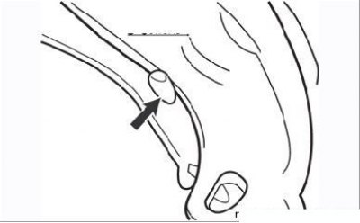
Figure 7.15. The stop protrusion on the parking brake release lever (arrow) should rest against the edge of the shoe
- make sure that the stop tab on the parking brake release lever rests against the edge of the release shoe (see Figure 7.15);
- install the assembled shoe assembly onto the brake shield. Insert the upper ends of the shoes into the slots of the brake cylinder pistons. Attach the parking brake tip to the working lever;
- install the lower tension spring on both pads and, overpowering the spring, install the pads with their lower ends in the support plate;
- moving the pads along the brake shield, center them and install the clamping devices on each one;
- use the adjusting mechanism knob to adjust the position of the shoes so that the brake drum can be placed on them with slight force;
- perform the same procedure with the brake drum on the other side of the car;
- do not tighten the hub nuts yet;
- adjust the position of the pads by pressing the brake pedal several times (about 20 times);
- ask an assistant to make sure that when you release the brake pedal, you can hear the clicking sound of the clearance adjustment mechanism in the drums;
- remove the brake drums;
- make sure that the stop tabs of both parking brake release levers rest against the edge of the release shoe, the parking brake cables move freely in the casing;
- with the help of an assistant, adjust the parking brake cable so that the levers on each brake shield begin to move between the first and second clicks of the ratchet mechanism of the parking brake lever in the passenger compartment of the car, i.e. so that at the first click the stop protrusion of the release lever still rests against the edge of the shoe, but at the second click it has already moved away from it;
- in this position, while holding the cable adjustment nut, tighten the lock nut securely;
- install the brake drums as described in the relevant subsection.