
Attention! The parts of the right and left brake mechanisms of the rear wheels are different from each other and therefore their rearrangement is not allowed. When installing the removed parts, they must be put in their original places.
Removing
1. Remove the brake drum.
2. Attach a spring clip, if any, to the top of the wheel cylinder to prevent the piston from coming out. Due to the fact that there is usually no clamp, when removing the brake pads, it is barely blowing to ensure that the piston is not removed. Otherwise, air will get into the brake system and it will have to be pumped.
Attention! With the brake pads removed, do not press the brake pedal, because the pistons will be squeezed out of the cylinders.
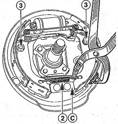
3. Record the mounting position of the shoe return springs before disconnecting them. This will make it easier to install later (see illustration).
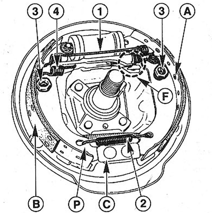
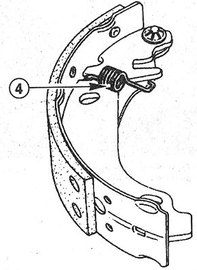
6.3 Right rear wheel brake
A - active (pressed) brake shoe
B - secondary (wringable) brake shoe
C - support
P - lower part of the brake shoe
F - device for automatic adjustment of the gap between the shoes and the brake drum
1 - upper coupling spring
2 - lower coupling spring
3 - support pin pads
4 - return spring of the expansion bar
4. Remove the lower return spring 2 using special spring removal pliers, e.g. HAZET 797 or using an adjustable wrench (see illustration).
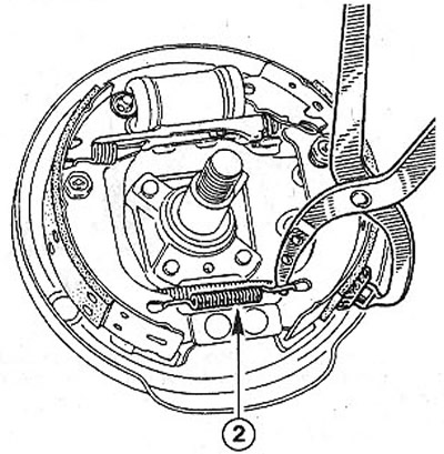
6.4 Remove the lower return spring 2 using special spring removal pliers
5. With a wrench, grip the clamp of the support pin of the guide spring R of the brake pads and, compressing the spring, turn the clamp 90°against the spring pressure (see illustration). When pushing, hold the support pin T on the back side of the shield E of the brake mechanism with your finger.
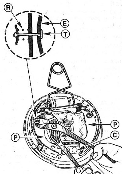
6.5 Using an adjustable wrench, grip the clamp of the support pin of the guide spring R of the brake pads and, after compressing the spring, turn the clamp 90°against the spring pressure
6. Release the brake pads P one by one isosupport C, squeezing the lower ends of the pads and sliding them over each other to separate the upper ones near the brake cylinder (see illustration 6.5).
7. Remove the brake pads together with the expansion bar and disconnect the parking brake cable.
8. Pull the parking brake cable lever outward (see illustration).
6.8 Move the parking brake cable lever outward
9. Disconnect spring E with a screwdriver (see illustration).
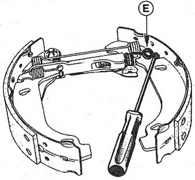
6.9 Disconnect spring E with a screwdriver
10. Separate the lower ends of the brake pads (see illustration). This will allow you to remove the upper return spring 1 without much effort.
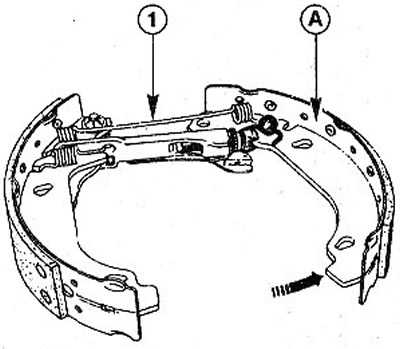
6.10 Separate the lower ends of the brake shoes
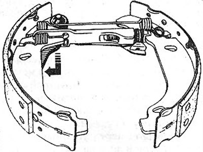
11. Pull the expander bar in the direction of arrow 1 as shown in the illustration, and then fold it down in the direction of arrow 2.
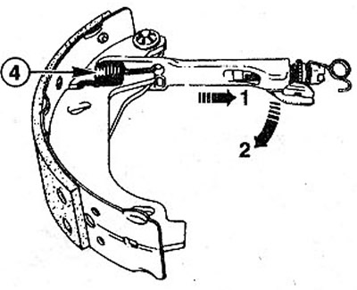
6.11 Pull the expander bar in the direction of arrow 1 as shown in the illustration, and then fold it down in the direction of arrow 2
12. Disconnect the spring 4 and remove the expansion plate (see illustration 6.11).
13. Unscrew the edge of the cuffs 1 and 2 on the wheel brake cylinder (see illustration). Check for moisture under the cuffs and, if necessary, replace the brake cylinder.
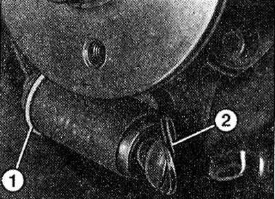
6.13 Turn off the edge of the cuffs 1 and 2 on the wheel brake cylinder
Attention! Make sure that when inspecting the cuffs, the piston does not come out of the cylinder.
Installation
Be sure to replace all four rear brake pads, even if only one is worn out.
Install brake pads of the same manufacturer and of the same quality on both wheels.
If the wheel brake cylinder is wet from the brake fluid flowing out of it, then it must be replaced.
Clean the expander bar threads and lubricate them with a thin layer of molybdenum grease. Give brake drums with a corrugated surface for boring. Be sure to bore both brake drums. Grinding of the surface of the brake drum is allowed by a maximum of 1 mm.
14. Clean the brake drum and brake support shield with compressed air or wipe with a rag soaked in alcohol.
Attention! When replacing parts of the expander bar, do not forget that they are mirror opposite on the left and right brake drums. On the left brake drum, the adjusting screw has a left-hand thread, the adjusting gear has two G slots. On the right brake gear, the gear has only one G slot, and the adjusting bolt has a right-hand thread (see illustration).
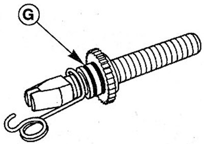
6.14 For the left brake drum, the adjusting screw has a left-hand thread, the adjusting gear has two grooves G. For the gear of the right brake mechanism, the gear has only one groove G, and the adjusting bolt has a right-hand thread
15. Check whether the spring 5 of the device for automatically adjusting the gap between the brake shoes and the drum is correctly installed (see arrow in illustration). The spring must not be caught between the head of the adjusting screw and the adjusting gear. There should be a gap J between them.
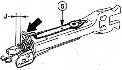
6.15 Check whether the spring 5 of the device for automatically adjusting the gap between the brake shoes and the drum is correctly installed (see arrow)
16. Make sure the locking bracket is seated correctly (see arrow in illustration).
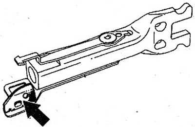
6.16 Check that the locking bracket is seated correctly (see arrow)
17. Screw in the adjusting bolt and place the clamp on the expansion bar. The spreading angle on the bar must be between the bracket and the bar (see illustration).
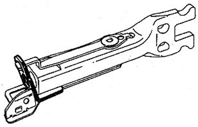
6.17 Expanding angle on the bar must be between the bracket and the bar
18. Attach the parking brake cable to the released (secondary) brake shoe with a new locking clip.
19. Fix the spring 4 in the groove of the brake shoe (see illustration). Observe the mounting position of the spring. It is attached with a short end to the brake shoe.
6.19 Fasten the spring 4 in the groove of the brake shoe
20. Put the expansion bar with the automatic clearance adjustment device on the brake shoe and fix the spring. Then pull the expander bar in the direction of arrow 1 while pushing it upwards at the same time as shown by arrow 2 (With. illustration). The spreader bar will take the desired position.
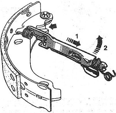
6.20 Pull the expander bar in the direction of arrow 1, simultaneously pushing it upwards, as shown by arrow 2
21. Fix the upper return spring 1 in the recesses on both brake shoes (see illustration).
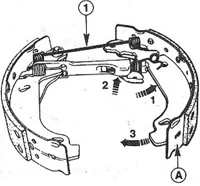
6.21 Attach the upper return spring 1 to the recesses on both brake shoes
22. Spread the brake pads (see arrow 1 in illustration 6.21) and insert the expander bar, see arrow 2. The notch on the bar must be on the protrusion of the active brake pad A (see illustration 6.21).
23. Compress the brake pads (see arrow 3 in illustration 6.21).
24. Place clamp E (see illustration).
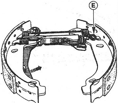
6.24 Attach clamp E
25. Pull the parking brake cable lever in the direction of the arrow in illustration 6.24.
26. Put the assembled brake mechanism on the support plate and fasten the parking brake cable to the lever.
27. Fix the top part of brake pads. Take some care not to damage the cuffs of the brake cylinder.
28. Fix the lower ends of the brake shoes on the support C (see illustration).
6.28 Fix the lower ends of the brake shoes on the support C
29. Secure the brake pads with support pins 3 with pressure springs (see illustration 6.28), holding the pins on the back of the brake shield and at the same time pressing on their clips with pliers. The pin clamps must be rotated 90°to secure the support pins.
30. Fix the lower coupling spring 2 on the brake shoes (see illustration 6.28).
31. Remove, if installed, the clamp from the brake cylinder to prevent the piston from coming out.
32. Adjust the expansion bar by turning gear P with a screwdriver until the diameter X formed by the outer surface of the brake pads is 202.5 - 202.7 mm (see illustration).
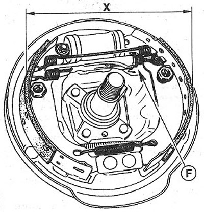
6.32 Adjust the expansion bar by turning gear F with a screwdriver until the diameter X formed by the outer surface of the brake pads is 202.5-202.7 mm
33. Reinstall the brake drum and tighten the hub nut by hand.
Attention! Do not tighten the hub nut because the brake drum will need to be removed.
34. Adjust the gap between the brake shoes and the drum by depressing the brake pedal several times (about 20 times). Clicks will be heard confirming the gap setting.
35. Adjust the tension of the parking brake cable, see the relevant chapter.
36. Install the brake drum.
37. Establish wheels according to the marks put at removal.
38. Screw in the wheel bolts and lower the car.
39. Tighten the wheel bolts in a cross pattern to 90 Nm.
Attention! Depress the brake pedal with force several times until a strong resistance is felt.
Attention! Make sure that:
- A) brake hoses are securely connected;
- b) brake hoses are fixed in holders;
- V) fittings for bleeding the brake actuator are wrapped;
- G) there is enough brake fluid in the expansion tank.
40. Perform a brake leak test by starting the engine.
To do this, depress the brake pedal with a force of 200-300 N (20-30 kg) and hold it for about 10 seconds. The pressure in the system and, accordingly, the resistance of the brake pedal, should not decrease. Check all connections for tightness.
41. Test drive on a light-traffic highway, braking a few times.