
The brake system consists of two circuits acting diagonally. One circuit of the brake drive acts on the front right and rear left wheels, and the other - on the front left and right rear. This ensures that the vehicle stops with sufficient efficiency in case of failure of one of the circuits of the service brake system, for example, due to leaks. The pressure for both circuits is provided by the brake master cylinder when the brake pedal is depressed.
The expansion tank, which provides the entire system with brake fluid, is located in the front of the engine compartment above the brake master cylinder.
The vacuum brake booster in vehicles with a gasoline engine uses the vacuum in the intake manifold and through the valves makes it possible to reduce the force on the brake pedal. Due to the lack of intake manifold vacuum in a diesel engine, vehicles with a diesel engine are equipped with an engine-driven brake booster vacuum pump.
The front and rear brake pads do not need to be adjusted.
The parking brake acts through a cable drive on the brake mechanisms of the rear wheels.
The brake force regulator on the rear axle regulates the braking force applied to the rear wheels and i te allows the rear wheels of an unladen vehicle to lock up during hard braking.
When cleaning the brake system, dust is generated. This dust is harmful to human health. Therefore, when cleaning the brake system, make sure that brake dust does not get into the respiratory tract.
Brake linings belong to the category of materials for which an operating permit is required and they are included in the General Operational Permit Register (AVE). In addition, they are selected by the manufacturer for certain car models. Therefore, it is recommended to use only linings offered by the RENAULT factory or approved by the Federal Automobile Administration. These pads have a number assigned to them by the Federal Automobile Administration.
Work on the brake system requires meticulous cleanliness and precision. If the necessary experience is not available, then it is better to entrust such work to a specialized workshop.
Anti-lock braking system (ABS)
Depending on the model and equipment, RENAULT MEGANE and SCENIC vehicles are equipped with an electronic anti-lock braking system TEVES MARK IV or BOSCH 5.3 (see illustration 1.0).
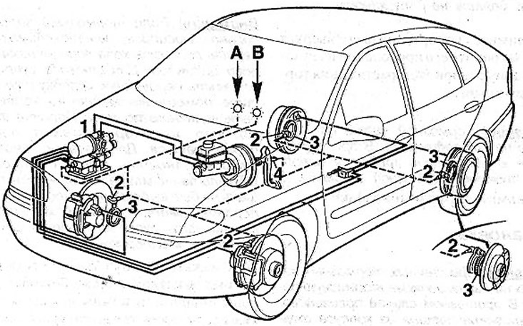
1.0 ABS Diagram:
—— hydraulic pipelines
- - - electrical wiring
A - ABS warning light
B - signal light for brake fluid level
1 - hydraulic block
2 - wheel speed sensor
3 - a gear that generates pulses during the rotation of the wheels for the wheel speed sensor
4 - sensor-switch of brake lights
Anti-lock braking system (ABS) consists of an electronic control unit and hydraulics, an ABS warning light on the instrument panel, wheel speed sensors and gears that generate pulses when the wheels rotate for the wheel speed sensor.
The anti-lock braking system prevents the wheels from locking during heavy braking. Thanks to this, the car remains steerable even with full braking. The driver feels the functioning of the anti-lock braking system by the pulsation of the brake pedal and the noise of the ABS hydraulic unit in the engine compartment.
The deactivation function in the ABS electronic control unit ensures that the system is automatically deactivated in the event of a defect, for example, when the power wire is broken or when the voltage in the on-board network drops below 10.5 V. The deactivation of the ABS is signaled by the light on the instrument panel. At the same time, the normal braking system continues to function and the car behaves like a car without ABS.
After the ignition is switched on, the ABS system performs a self-test. After about 3 seconds, the warning light on the instrument panel should go out. If the warning light stays on or lights up while driving, do the following.
1. Stop, stop the engine and check the battery voltage. If it is less than 10.5 volts, then charge the battery.
2. Check whether the terminals of the power wires are securely fastened to the battery poles.
3. Place the vehicle on jack stands and remove the wheels. Check the wires of all four wheel speed sensors for external damage (grinding).
4. Disconnect the wheel speed sensors and clean them with AUTOLUBE (see illustration). Then connect the plugs.
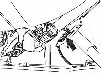
1.4 Disconnect the wheel speed sensors and clean them with AUTOLUBE. The illustration shows the rear wheel connector. It's next to the shock absorber
Further checks of the ABS must be carried out in a workshop. The ABS control unit runs a self-diagnosis program and all faults are logged. These faults can be read in the workshop using a special tester, and then eliminated.
Attention! When working with electric welding, you must disconnect the plug of the ABS electronic control unit. Disconnect the plug only when the ignition is off. When painting, the control unit can be exposed to temperatures not exceeding +85°C.