
Always reinstall body heat shields. Observe the recommended tightening torques for threaded connections. Wear protective clothing and goggles when carrying out repairs.
The car body is welded, all-metal, bearing structure. The bottom, sides and roof are welded together. Hood, trunk lid (tailgate), doors and front fenders are bolted on and can be easily replaced.
The body is a three- or five-door hatchback, for some markets a station wagon model is produced.
To enhance the carrying capacity of the body, a subframe is used to mount the power unit, suspension and steering mechanism.
The front wings of all models are made of a polymer that can withstand a frontal impact without visible damage at speeds up to 16 km/h.
All new cars have effective protection of the body and bottom against corrosion. Various technologies are used for this, such as galvanization, zinc phosphate coating and priming. An anti-gravel coating is applied to the front of the hood. For the treatment of box-shaped and hidden cavities, wax formulations are used.
There are many plastic elements in the body structure - bumpers, wheel mudguards, radiator grille, etc.
The gaps between the body parts must be the same along the entire length. When installing new removable elements, it is very important to comply with the clearances and tolerances established by Renault, otherwise the installed elements may jam or the noise level in the body may increase sharply. In addition, the aesthetic standards for the car are violated.
Body gaps
Shown on the example of Renault Clio
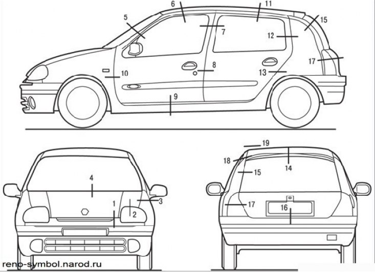
Figure 9.1. Gap control zones between the body and removable body elements
Figure 9.1 shows the areas of the vehicle for which controlled gaps are set between the body and its removable elements, and Figures 9.2a and 9.2b show the clearance values.
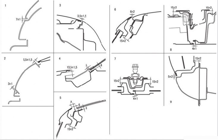
Figure 9.2a. Gaps in interfaces of a body and removable elements
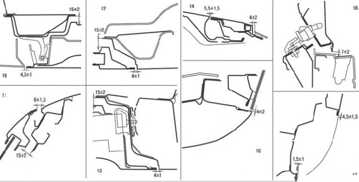
Figure 9.2b. Gaps in interfaces of a body and removable elements
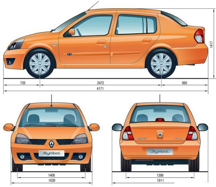
Body dimensions
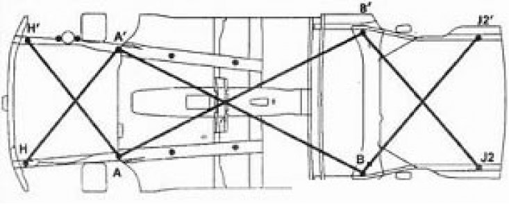
Reference points for verification of collision consequences
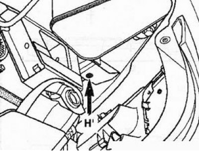
Point H: Front end of the front side member.
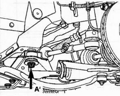
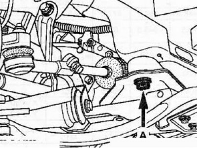
Point A: Front subframe rear support.
(On right).
(Left).
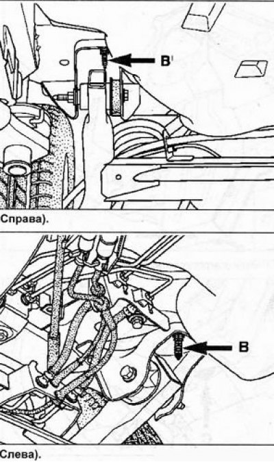
Point B: Front end of the rear axle beam.
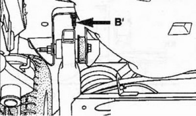
(On right).
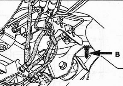
(Left).
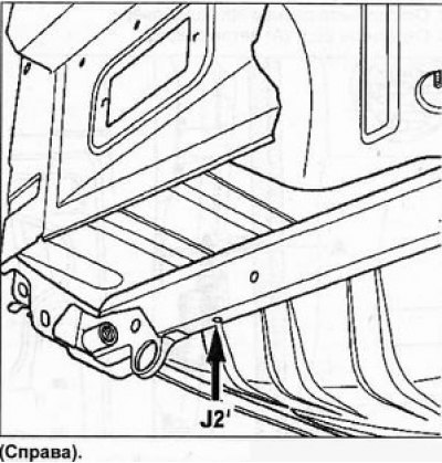
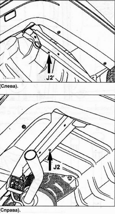
Point J2: Rear end of the rear spar.
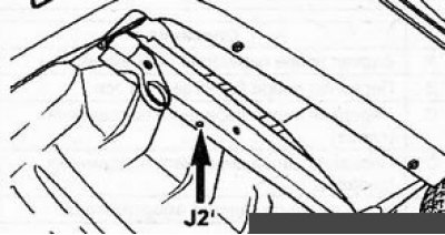
(On right).
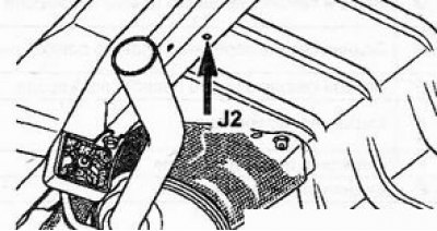
(Left).
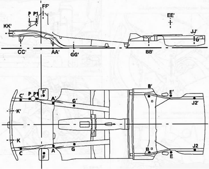
| Description | X | Y | Z | 0 | corner | |
| A | Rear support of the front subframe | 205 | -402,5 | 71 | 18,5 | 0 |
| IN | Front support of the rear axle beam | 2012 | -530 | 129 | 16,2 | 0 |
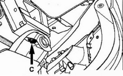
| WITH | Front subframe support (left) | -418 | -447 | 130 | 10 x 10 square | 0 |
| WITH' | Front subframe support (on right) | -418 | 465 | 130 | 10 x 10 square | 0 |
| E | Rear shock absorber upper support | 2448,5 | -534,5 | 477,5 | 18,2 | 0 |
| F | Front shock absorber upper support | 18,5 | -545,5 | 657 | 48 | X: 3°02' Y: 1°00' |
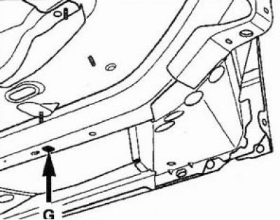
| G | Rear section of the front left side member | 600 | -375 | -3,7 | 20 x20 square | 0 |
| G' | Rear section of front right pongeron | 600 | 351,5 | -5 | 20x20 square | 0 |
| J2' | Rear section of rear right side member | 3040 | 481 | 162,5 | 10,2 | 0 |
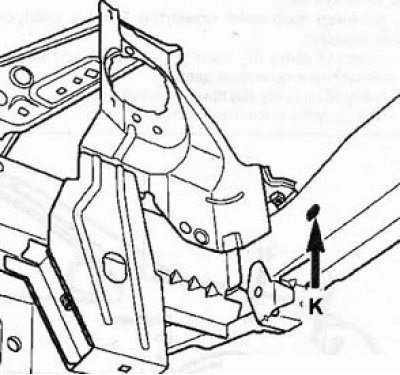
| TO | front cross member | -575 | 315 | 280 | 14,25 | X: 4°30' Y: 5°00' |
| R | Front engine support | -247 | 483,5 | 514 | M10 | 0 |
| R' | Rear engine support | -113 | 483,5 | 514 | M10 | 0 |
Subframe dimensions
Anchor points
A - rear support of the front subframe
Main anchor point in the front.
1. The power unit is removed.
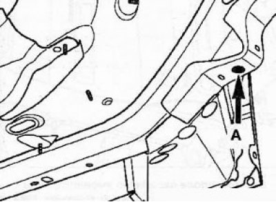
The measuring tool is installed in the center of the hole.
Note. The hole on the left is round, the hole on the right is oval.
2. The power unit is installed.
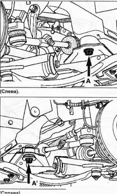
Note. The fasteners on the left and right are not symmetrical.
The support on the left is mounted on a rubber cushion.
B - Front support of the rear axle beam
Main anchor point at the back.
1. Beam removed.
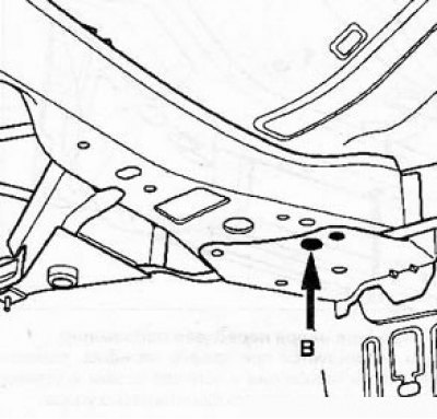
2. The beam is installed.
G - Rear section of the front left side member
This point is used for reference when replacing the rear part of the spar and as a reference point for measurements at damaged points A and B.
C - Front support of the front subframe
The dot is used when replacing the front cross member. parts of the pongeron and strut tunnel and assessment of deformations due to a light frontal impact.
1. The power unit is removed.
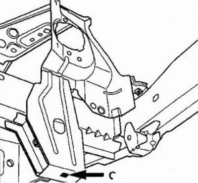
2. The power unit is installed.
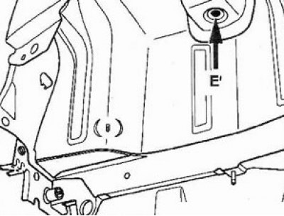
E - The upper support of the rear shock absorber
The point is used when replacing the wheel arch.
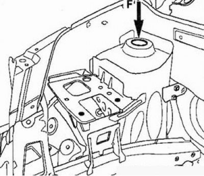
F - Front shock absorber upper support
The point is used when replacing the wheel arch and strut tunnel and control when editing the body.
J2 - Rear section of rear right side member
1. Beam removed.
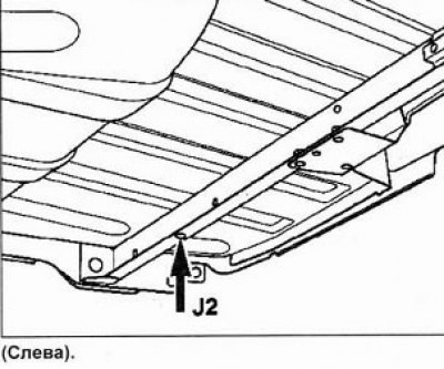 |  |
2. The beam is installed.
K - Front cross member
The point is used when replacing the front cross member with the power package removed or installed (radiator must be removed).
Special tools for bodywork
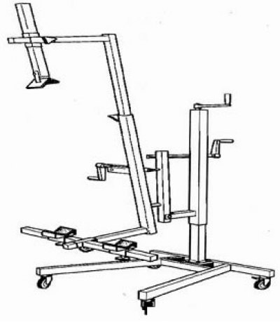
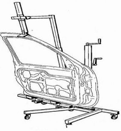
1. Door remover/installer 661 000 with adapters.
 |  |
2. Tools for removing/installing glued glass.
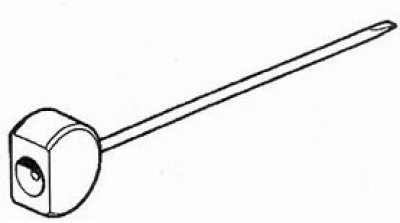
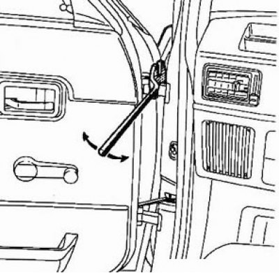
A) Wiper arm puller.
b) Sealant cutting wire.
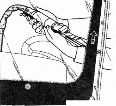
V) Pneumatic knife for cutting sealant.
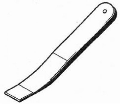
G) Remover of overlay panels and seals.
d) Panel clip remover.
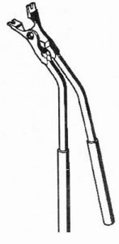
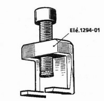
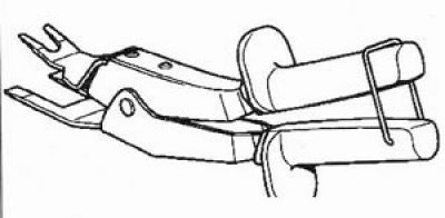
e) Door hinge pin remover.
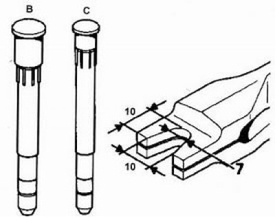
and) Modified door hinge pin puller (Clio models (IN) and Megane (WITH)).
h) Lever for adjusting the gaps of overhead body elements.
And) Door adjustment device.