
Removing
Place the car on a two post lift.
Disconnect the battery.
Install a tool on the brake pedal to reduce the amount of brake fluid escaping.
Drain the refrigerant from the refrigeration circuit.
Remove the engine top covers.
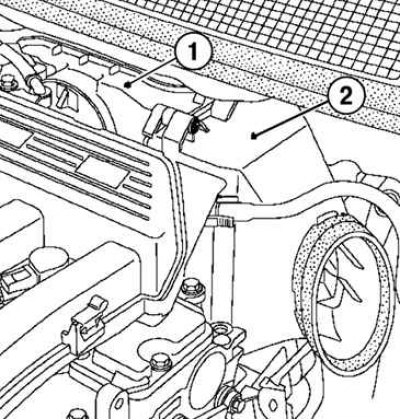
Pic. 6.85. Attaching the air filter access panel: 1 - fastening bolts
Remove the two bolts securing the air filter access panel (pic. 6.85).
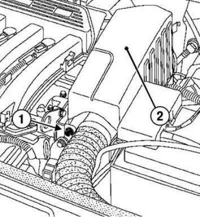
Pic. 6.86. Removing the intake silencer: 1 - fastening bolt; 2 - intake silencer
Loosen the intake silencer bolt and remove it (pic. 6.86).
Attention! Be careful not to damage the suction pipe on the intake manifold. If it breaks, replace the intake manifold.
Disconnect the brake booster vacuum hose from the intake manifold.
Disconnect the wire blocks from the ignition coils.
Disconnect the wiring harness from the throttle body.
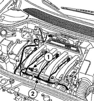
Pic. 6.87. Disconnecting the wiring harness from the air temperature sensor: 1 - block of wires of the air temperature sensor; 2 - wiring harness
Disconnect the wiring harness from the air temperature sensor (pic. 6.87).
Disconnect the wiring harness from the holders on the engine.
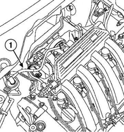
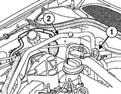
Pic. 6.88. Disconnecting the evaporative emission system hose: 1 – a hose of system of catching of steams of fuel
Disconnect the evaporative emission system hose from the holders (pic. 6.88).
Loosen the air filter housing bolt. Do not remove the filter housing from the engine compartment.
Pic. 6.89. Removing the filter element and air filter housing: 1 - filter element; 2 - air filter housing
Remove the filter element and air filter housing (pic. 6.89).
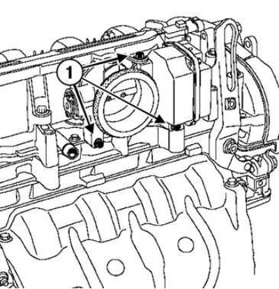
Pic. 6.90. Removing the throttle body: 1 - fastening bolts
Loosen the mounting bolts and remove the throttle body (pic. 6.90).
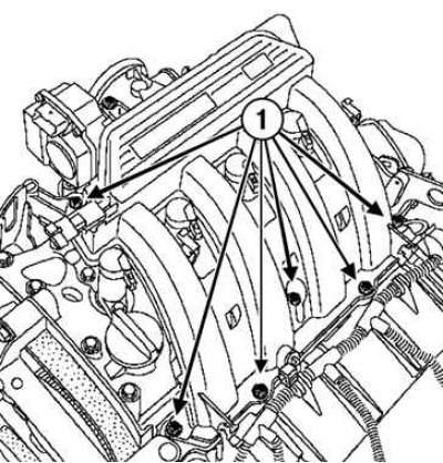
Pic. 6.91. Removing the intake manifold mount: 1 - fastening bolts
Loosen the mounting bolts and remove the intake manifold (pic. 6.91).
Remove the noise barrier fasteners, and then the screen itself.
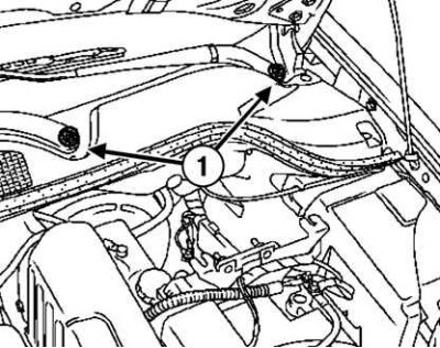
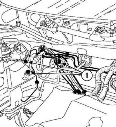
Pic. 6.92. Removing the lifting eye and the refrigeration circuit piping of the air conditioner: 1 - lifting eye; 2 - pipeline of the refrigeration circuit of the air conditioner
Remove the lifting eye and the A/C refrigeration circuit piping between the flange on the bulkhead and the receiver-drier (pic. 6.92).
Remove the wire lug bolt «masses» ABS ECU.
Disconnect the ECU connector.
Loosen the fittings securing the pipelines to the hydraulic unit.
Disconnect the pipelines from the hydraulic unit.
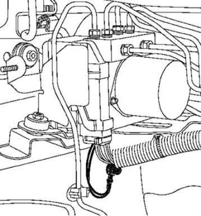
Pic. 6.93. Removing the valve body bracket: 1 - fastening bolts
Loosen the bolts securing the hydraulic unit bracket (pic. 6.93).
Remove the hydraulic block assembly with the bracket.
Unscrew the bolts securing the hydraulic unit to the bracket and remove the hydraulic unit.
Installation
Installation is made in an order, the return to removal.
Pic. 6.94. Installation of the hydroblock
Attention! Point the tip of the wire «masses» valve body down to ensure the tightness of the valve body ECU connector (pic. 6.94).
Install the air conditioning refrigeration piping.
Torque tighten:
- hydraulic unit bracket mounting bolts (6.5 Nm);
- bolts of fastening of pipelines on the hydroblock (14 Nm);
- intake manifold bolts (9 Nm);
- bolts for fastening the hydraulic unit to the bracket (8 Nm).
Note. Replace the gasket each time the throttle body is removed.
Note. Be sure to replace the gaskets at the ends of the refrigeration circuit piping of the air conditioner.
Remove air from the brake system.
Connect the battery.
Re-initialize the programmed throttle limits.
Fill the refrigeration circuit with refrigerant.
Check the operation of the air conditioning system with the passenger compartment fan operating at maximum speed.
If the cabin air is not cooled, look for a refrigerant leak.
Electric pump assembly
Note. Cars are equipped with two types of electric pumps: for the ABS system, or for the ABS system combined with the trajectory stabilization system.
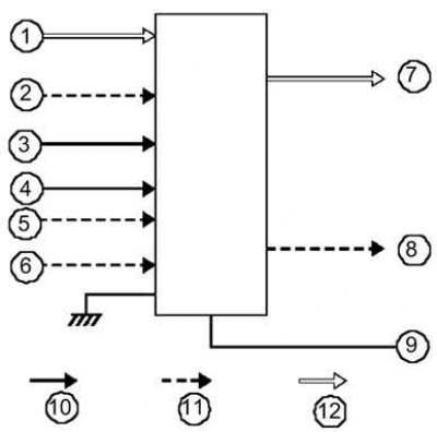
Pic. 6.95. Schematic diagram of the electric pump