
The main components of the heater:
- heater heat exchanger (radiator), designed to heat the air entering the passenger compartment with the heat of the engine cooling liquid;
- electrically driven fan (supercharger), providing an adjustable supply of outside air to the dampers of the heater and air conditioner;
- the damper for the temperature regulator of the air coming from the heater to the passenger compartment, the amount of air passing through the heater heat exchanger and outside air passing bypassing the heat exchanger depends on the change in its position;
- dampers for distributing air from the heater through air ducts to the passenger compartment or for blowing the windshield.
The purpose and operation of the air conditioner controls are described in Sec. 1 «Vehicle device», cm. «Heating (conditioning) and interior ventilation».
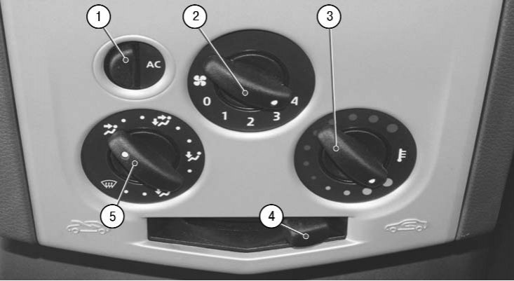
1.9. Heating control unit (conditioning) and interior ventilation
Switch 2 (see fig. 1.9) operating modes of the fan operates regardless of the position of the air distribution regulator 5 and the temperature regulator 3 and controls the fan speed by changing the voltage in the electric motor power supply circuit.
The air conditioning system includes the following elements.
The compressor is belt driven by the engine crankshaft pulley. A friction electromagnetic clutch is built into the compressor pulley, which disconnects the compressor shaft from the pulley or connects them when the air conditioner is operating at the signal of the electronic engine control unit. During operation, the compressor compresses to high pressure the refrigerant vapor coming to it from the evaporator heat exchanger. The temperature of the refrigerant vapor at the compressor outlet is much higher than at the inlet.
The pressure reducing valve is built into the compressor and performs a protective function, triggering when the pressure rises above the permissible value at the compressor outlet. The pressure reducing valve may be triggered by failure of the high pressure valve, electric fan, etc.
heat exchanger (radiator) condenser, located behind the radiator of the engine cooling system and having a coil with developed fins for rapid cooling and condensation of the refrigerant vapor compressed by the compressor to high pressure.
Throttle pipe (reducer) with mesh filters at the inlet and outlet is installed in the pipeline supplying the liquid refrigerant to the evaporator heat exchanger. The orifice in the nozzle limits the flow of liquid refrigerant and reduces the pressure in the evaporator. After the engine is stopped, the liquid refrigerant continues to flow through the throttle pipe from the high pressure zone to the low pressure zone for some time. The flow of fluid through the throttle hole is accompanied by a characteristic hissing sound, which is heard for 30-60 seconds after the engine is stopped and does not indicate a malfunction.
heat exchanger (radiator) evaporator. The liquid refrigerant from the condenser heat exchanger enters through the throttle pipe into the evaporator heat exchanger located in the heater block. In the heat exchanger, the liquid passes into a gaseous state, absorbing heat. The moisture contained in the air entering the heat exchanger condenses on it, flows off the evaporator and is removed from the heater unit. From the evaporator heat exchanger, the gaseous refrigerant with an admixture of a small amount of the liquid refrigerant fraction and drops of refrigerant oil enters the receiver, which is connected to the evaporator outlet pipeline.
Receiver dryer. In the lower part of the receiver housing there is a container with a water vapor absorber from the refrigerant vapors, which, being freed from moisture through a special hole in the intake tube, are mixed with refrigerant oil. In the upper part of the receiver housing there are fittings for connecting pipelines. The receiver is not repairable, it needs to be replaced only as an assembly.
In addition to the listed elements, the system includes high and low pressure valves and pressure sensors.
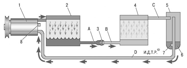
11.2. Schematic diagram of the movement of the refrigerant in the air conditioning system: 1 - air conditioning compressor; 2 – condenser heat exchanger; 3 - throttle branch pipe (reducer); 4 – evaporator heat exchanger; 5 - receiver-drier; 6 - moisture absorber in the receiver; 7 - hole for mixing refrigerant vapor with refrigerant oil; 8 - pressure reducing valve in the compressor; A - liquid refrigerant under high pressure; B - liquid refrigerant under low pressure; C - gaseous refrigerant under high pressure; D - low pressure gaseous refrigerant
A schematic diagram of the movement of the refrigerant in the air conditioning system is shown in fig. 11.2.
Attention! All work on the repair of the air conditioning system should only be carried out with a completely discharged system. Since refrigerant fumes are toxic, repair the system using special equipment available from specialized air conditioning services.
Note. Due to the specific features of the repair of the air conditioning system (see warning above) this subsection describes only the repair of the heater: removal and installation of the heater radiator and the control unit for the air conditioning and heating system.