



1. Disconnect the wire from the negative terminal of the battery.
2. Remove the steering wheel (see "Removing and installing the steering wheel").
3. Remove the steering column switches assembly with the connector (see "Checking and replacing steering column switches").
4. Remove the instrument cluster (see "Removing and installing the instrument cluster").
5. Remove the floor tunnel lining (see "Removal and installation of floor tunnel lining").
6. Remove the front body pillar trims (see "Removal and installation of interior trim").
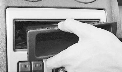
7. Remove the radio socket plug from the instrument panel trim...
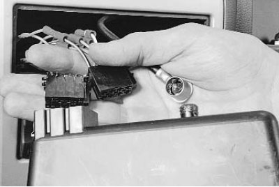
8. ...disconnect the wiring harness connectors and the antenna cable from the plug and remove the plug.
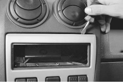
9. Carefully pry up the edge of the central instrument panel trim with a screwdriver...
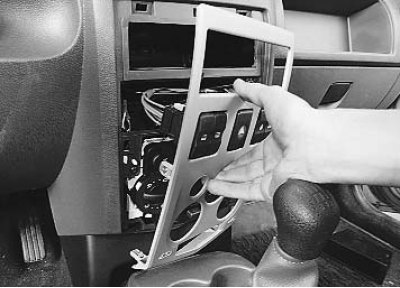
10. ...and, overcoming the resistance of its spring clips, detach the trim from the instrument panel.
Caution! Be careful, as the clips are very rigid and excessive force can damage the appearance of the trim or instrument panel.
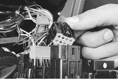
11. Squeeze the clamps and disconnect the wiring harness connectors from the front door window switches, central lock, rear window heating, and hazard warning lights, and remove the central instrument panel trim.
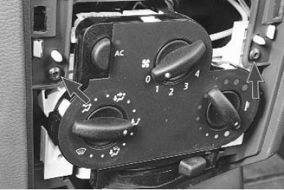
12. Remove the two screws securing the heating, air conditioning and ventilation control unit to the instrument panel.
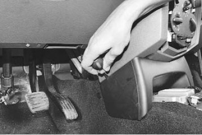
13. Using a screwdriver, pry up the edges of the lower instrument panel trim and detach the spring clips...
Original publication on the portal www.renaultbook.ru
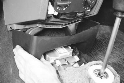
14. ...and remove the cover.
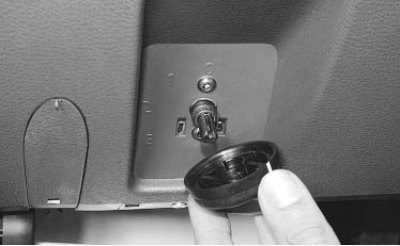
15. Pull the headlight corrector handle towards you and remove it.
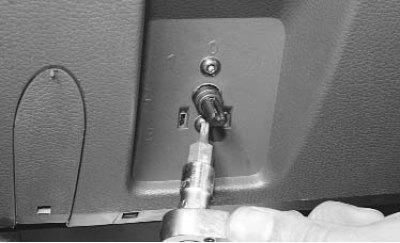
16. Remove the two screws securing the headlight range control switch and push the switch under the instrument panel.
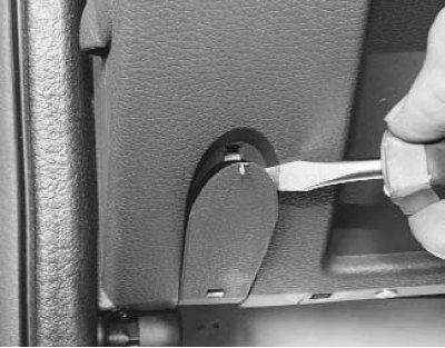
17. Using a screwdriver, pry off the decorative plugs of the screws of the lower fastening of the instrument panel on the left and right.
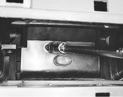
18. Remove the instrument panel mounting screw in its central part (the screw is accessible through a window in the panel that opens after removing the center trim)...
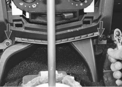
19. ...two screws for fastening to the bracket on the base of the body...
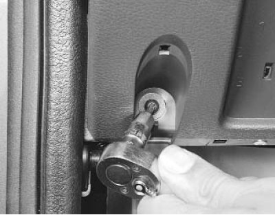
20. ...two lower screws of the side mounts, located on the left and right...
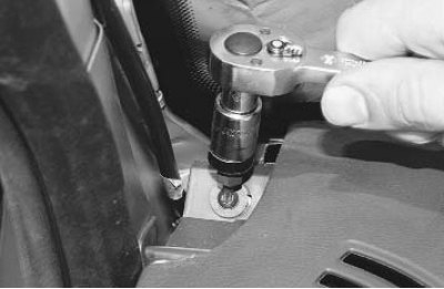
21. ...two upper screws of the side mounts, located on the left and right...
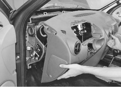
22. ...and remove the instrument panel, removing the diagnostic connector from the glove compartment socket during the removal process.
23. Install the instrument panel and all removed parts and assemblies in the reverse order of removal.