1. Disconnect the wire from the negative terminal of the battery.
2. Remove the steering column cover, see. "Removing and installing the ignition switch (lock)".
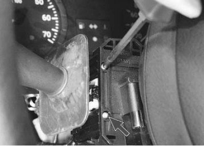
3. Remove the two screws securing the steering column switch...
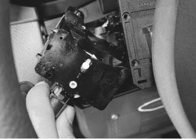
4. ...and remove it from the connector socket.
[The text is available on this website: RENAULTBOOK.ru]
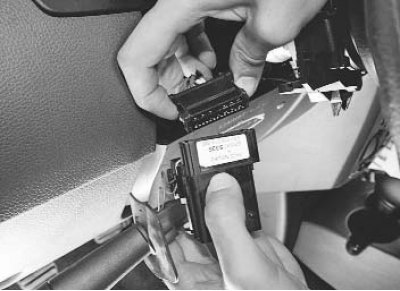
5. Disconnect the wiring harness connector from the switch.
6. Remove the second steering column switch in the same way.
7. Install the switches and all parts in the reverse order of removal.
Removal steering column switches assembly with the connector, follow the following order.
1. Disconnect the wire from the negative terminal of the battery.
2. Remove the steering wheel (see "Removing and installing the steering wheel").
3. Remove the steering column cover, see. "Removing and installing the ignition switch (lock)".
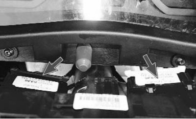
4. Disconnect the wiring harness connectors from the steering column switches.
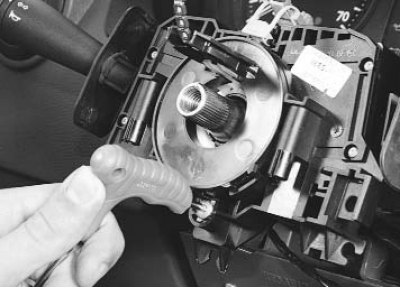
5. Unscrew the bolt of the connector mounting clamp...
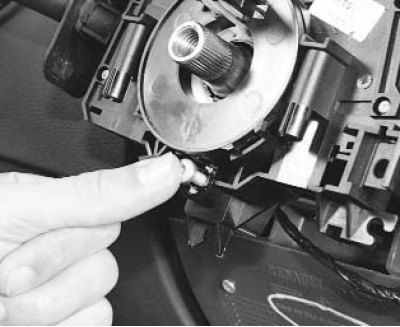
6. ...and press on it to loosen the clamp.
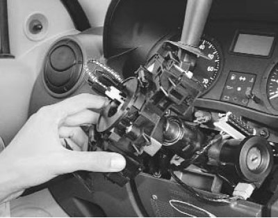
7. Remove the connector assembly with the steering column switches.
8. Install the parts in the reverse order of removal.
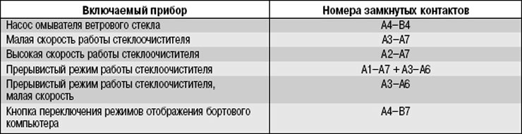
The serviceability of the steering column switches is determined by checking the correctness of the contacts at different positions of the levers. Remove the switches for testing and connect a 12 V test lamp (with current source) or an autotester with a circuit "continuity" function to the corresponding terminals specified in Tables 10.3 and 10.4. Move the switch lever to the position corresponding to the contacts being tested – the lamp should light. Otherwise, the switch is faulty.
The switch terminal numbers are shown in Figures 10.4 and 10.5.
Table 10.3. Contact closure at different positions of the exterior lighting and turn signal switch lever with horn button
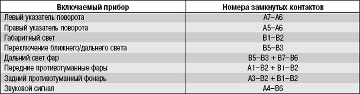
Table 10.4. Contact closure at different positions of the windshield wiper and washer switch lever with the trip computer display mode switching button