English Русский
Български
Беларускі
Український
Српски
Hrvatski
Română
Polski
Slovenský
Magyar
Bookmark Contacts Articles Sitemap
Company vehicles Peugeot Company vehicles Opel Company vehicles Skoda Company vehicles Land Rover Company vehicles Mitsubishi Company vehicles Volkswagen Company vehicles Honda
RenaultBook.ru


Duster   Fluence   Kangoo   Laguna   Logan   Megane   Sandero   Scenic   Symbol   Clio   Other
Logan 1 (2004-2012, petrol) Logan 2 (2012-2020)

Location of fuses, fuse links and relays and their replacement (Renault Logan 1)

  • Main
  • Logan
  • Logan 1 (2004-2012, petrol)
  • Electrical equipment
  • Equipment and devices
  • Location of fuses, fuse links and relays and their replacement
0
Most of the power circuits of the car's electrical equipment are protected by fuses. Headlights, fan motors, fuel pump and other powerful consumers are connected via relays. Fuses and relays are installed in mounting blocks, which are located in the car's interior on the left side of the instrument panel and in the engine compartment on the left and right sides of the battery.

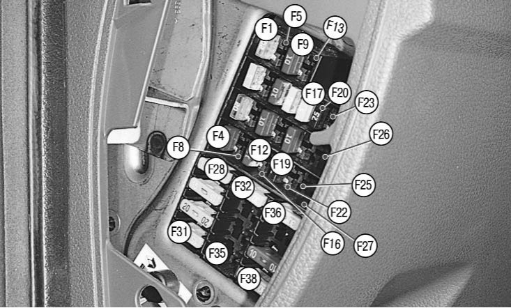
10.1. Fuse numbers in the fuse box located in the passenger compartment

10.1. Fuse numbers in the fuse box located in the passenger compartment


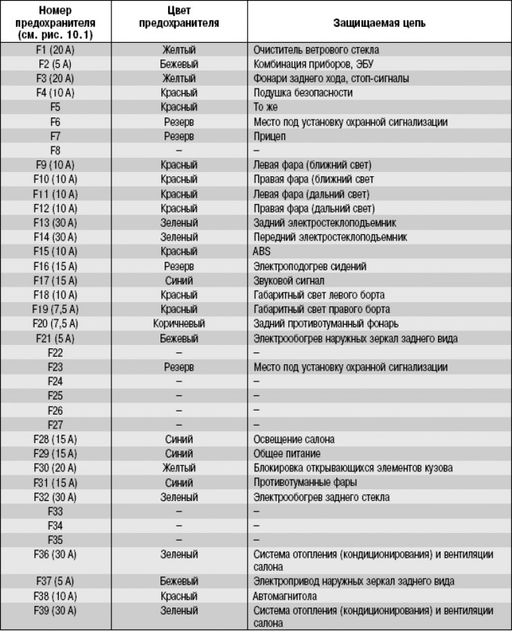
Most fuses are located in the passenger compartment fuse box (figure 10.1, the cover of the block in the instrument panel is removed), located at the left end of the instrument panel under a plastic cover. Circuits protected by fuses (shown in the photo), are given in Table 10.1.

Table 10.1. Circuits protected by fuses.


(Text of the original source on this website: renaultbook.ru)

Table 10.1. Circuits protected by fuses.

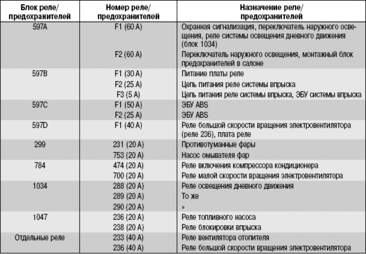
In addition, relays and fuses are located in the mounting block in the engine compartment (figure 10.2, mounting block cover removed). Table 10.2 shows the block designations and the purpose of the installed relays and fuses. It should be borne in mind that a specific car model may not have some of the circuits listed in the table, and the positions of the blocks may differ.
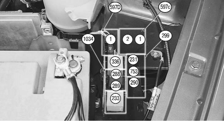


10.2b. Relay and fuse numbers in the mounting block located in the engine compartment (left side)
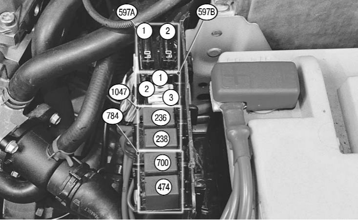
10.2b. Relay and fuse numbers in the mounting block located in the engine compartment (left side)


10.2a. Relay and fuse numbers in the mounting block located in the engine compartment (right side)

10.2a. Relay and fuse numbers in the mounting block located in the engine compartment (right side)


Table 10.2. Purpose of relays and fuses in the mounting block located in the underhood space (Figure 10.2a, 10.2b)


Table 10.2. Purpose of relays and fuses in the mounting block located in the underhood space…

1. To gain access to the mounting block, remove the cover in the instrument panel.
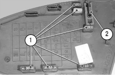


1. To gain access to the mounting block, remove the cover in the instrument panel.


Note: On the inside of the cover there is a diagram of the location of the relays and fuses, as well as spare fuses 1 of different ratings and plastic tweezers 2 for removing fuses from the mounting block.


2. Before replacing a blown fuse, find out the reason for its blown fuse and eliminate it. When searching for a fault, look at the circuits specified in Table 10.1 that this fuse protects.

Warning! Do not replace fuses with jumpers or fuses rated for a different current, or with homemade jumpers - this may damage electrical equipment and even cause a fire.


3. Remove the replacement fuse using tweezers.

3. Remove the replacement fuse using tweezers.


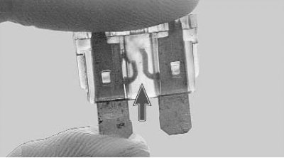
4. This is what a blown fuse looks like (the jumper shown by the arrow inside the holder has burned out and opened). To replace a fuse, use a spare fuse of the same rating (and color).


Note: Spare fuses of different ratings are located on the back of the mounting block cover.


Note: Spare fuses of different ratings are located on the back of the mounting block cover.


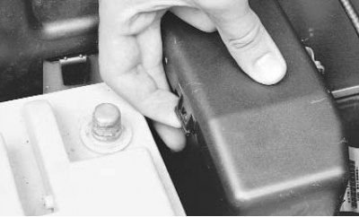
5. To access the mounting block located in the engine compartment, press the left...
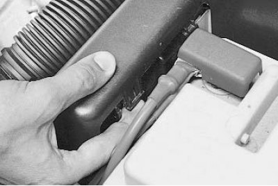
5. To access the mounting block located in the engine compartment, press the left...


6. ...and the right cover clamps...

6. ...and the right cover clamps...


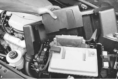
7. ...then remove the mounting block cover.

8. If replacement is necessary, remove the relay (fuse), rocking it from side to side.

9. Install the parts in the reverse order of removal.
This article is available on: russian, bulgarian, belarusian, ukrainian, serbian, croatian, romanian, polish, slovak, hungarian
Article has been reviewed by editor: Podkrepilov Maxim
Share with friends:
Previous
Logan 1: Equipment and devices
Next

Diagnostics of faults of on-board electrical equipment
Design features of on-board electrical equipment
Features of the ignition switch design
Checking the ignition switch (lock)
Removal and installation the ignition switch (lock)
Checking and replacing steering column switches
Removal and installation the horn
Other articles on other Renault models

➽ Mounting blocks — location of fuses, fuse links and relays and… Renault Sandero 1 (2007-2012, petrol)
➽ Fuses and relays — location and ratings Renault Symbol 2 (2008-2013, petrol)
➽ Fuses and relays Renault Kangoo 1 (1997-2007)
➽ Box with fuses and relays Renault Laguna 2 (2001-2007)
➽ General description of fuses and relays Renault Megane 1 (1995-2002)
Link to this article in different formats
Reviews and comments of visitors
No comments yet


Add two numbers 17 + 50


Logan 2 (2012-2020) 
  • General information
  • Faults en route
  • Daily checks
  • Governing bodies
  • Maintenance
  • Power unit
  • Petrol engines 1.2 l
  • Petrol engines 1.6 l
  • Diesel engines 1.5 l
  • Cooling system
  • Lubrication system
  • Power and control system
  • Intake and exhaust system
  • Engine electrical equipment
  • Transmission
  • Clutch
  • Car gearbox
  • Drive shafts
  • Chassis, running gear
  • Suspension and wheels
  • Brake system
  • Steering
  • Body and interior
  • Exterior (external elements)
  • Interior (internal elements)
  • Safety system
  • Heating and air conditioning
  • Electrical equipment
  • Equipment and devices
  • Wiring diagrams (sedan)
  • Wiring diagrams (wagon)
Logan 1 (2004-2012, petrol) 
  • General information
  • Vehicle device
  • User manual
  • Faults en route
  • Daily maintenance
  • First maintenance
  • Second maintenance
  • Driver tips
  • Power unit
  • Engine repair
  • Lubrication system
  • Cooling system
  • Power and exhaust system
  • Transmission
  • Clutch
  • Car gearbox
  • Drive shafts
  • Chassis, running gear
  • Front suspension
  • Rear suspension
  • Steering
  • Brake system
  • Wheels and tires
  • Body and interior
  • Exterior (external elements)
  • Interior (internal elements)
  • Doors, locks and windows
  • Body Care
  • Electrical equipment
  • Equipment and devices
  • Headlights and lighting
  • Power devices
  • Electrical circuits
RenaultBook.ru © 2018–2026 | Mobile version | News and articles | Sitemap: EN BG BY UA RS HR RO PL SK HU | Administration | Site search | Bookmark
Duster 1 (2009-2017) | Fluence 1 (2009-2020, petrol) | Kangoo 1 (1997-2007) | Laguna 2 (2001-2007) | Logan 1 (2004-2012, petrol) | Logan 2 (2012-2020) | Megane 1 (1995-2002) | Megan 2 (2002-2009, petrol) | Sandero 1 (2007-2012, petrol) | Scenic 1 (1996-2003) | Symbol 1 (1999-2008, petrol) | Symbol 2 (2008-2013, petrol) | Renault 19 (1988-1996) | Espace I and II (1984-1996) | Espace III (1996-2002) | Clio 1 (1990-1998) |
We want your visit to be comfortable 😌 and use cookies 🍪 to do so.