
Cars of the 1st and 2nd stages of production
Removing
1. Disconnect the wire «masses» from the battery.
2. Remove a steering wheel, the block of understeering switches and a combination of devices.
3. Turn away two screws from each party and take the lower casing from under a steering column.
4. Remove the two remaining screws on the right that secure the pedal assembly trim and remove it. Disconnect the connector from the lighting control, and in cars of later releases, remove the hood lock drive handle. Remove the pedal assembly cover.
5. In cars of later releases turn off 2 screws of fastening of the handle of a drive of the lock of a cowl on the lateral lower panel.
6. Remove the 4 nuts securing the steering column to the bracket and lower the column down until the swivel is accessible and can also move down as far as possible.
7. Working through the opening in the instrument panel, unscrew the 4 screws (2 at the top and 2 in the center) and remove its bottom cover.
8. Open the fuse block housing by removing the two nuts. Using a screwdriver, remove the axle and pull out the instrument panel housing.
9. Remove the two screws securing the right side panel (at the bottom).
10. On early production vehicles, remove the 4 screws on each side and remove the left side covers from the bottom center of the instrument panel. On older vehicles, remove the trim, remove 2 screws on each side, then remove the two side panels from below the center of the instrument panel.
11. Determine the location of the two control cables for the heating and ventilation system, sketch their position to facilitate subsequent assembly. Disconnect the cables from the damper levers.
12. Remove 2 bolts on each side that secure the bottom panels of the front panel to the door pillars (see illustration).
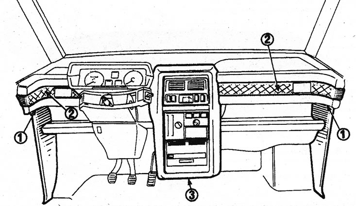
23.12 Location of screws securing the front panel and adjacent elements (cars of the 1st and 2nd stages of production) 1. Screws for fastening the side panels to the door pillars; 2. Screws for fastening the central trim; 3 Center panel fixing screws
13. Carefully remove the air ducts from each side of the front panel.
14. Turn away the screw in the middle from below the central console.
15. Remove the screws on each side of the front panel.
16. Lift up the front panel to access the front studs.
17. After removing the front panel from the studs, disconnect all electrical connectors, having previously marked them.
18. After removing the front panel, you can remove the top panel: to do this, unscrew the fastening screws at the base of the windshield and along the upper edge of the cross member.
Installation
19 Installation is carried out in the reverse order. In doing so, do the following:
- A) make sure that all electrical connectors are connected correctly;
- b) Adjust the control cables for the ventilation and heating system. To do this, move the intake air temperature control lever to the position «FROID» («COLD») and check that the cold air damper is closed. Connect the end of the cable to the damper lever, then secure the outer cable with a clamp. Adjustment is made by slightly moving the cable in its clamp in the desired direction. Move the intake air distribution control lever to the lower position and check that both air distribution dampers are closed;
- With) reinstall the steering wheel (see chapter 19), instrument panel and steering column switch block (see chapter 21).
Cars of the 3rd stage of production
Removing
Attention: In vehicles equipped with an airbag, some of the following operations require intervention in individual elements of the airbag. All these operations must be carried out at a Renault workshop.
20. Disconnect the wire «masses» from the battery.
21. Remove the steering wheel and instrument panel (see chapters 19 and 21).
22. Carefully remove the speaker grid in the upper corner of the instrument panel. Disconnect the wire if necessary (see illustration).
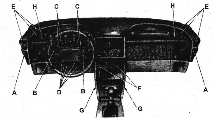
23.22 Location of screws securing the front panel and adjacent elements (cars of the 3rd stage of production) A Side panel fixing screws; B Screws for fastening the frame of the instrument panel; C Screws for fastening the instrument cluster; D Steering column lower cover screws; E Top panel fixing screws; F Upper center panel fixing screws; G Lower center panel fixing screws (located in air ducts); H Top panel to cross member screws
23. Unscrew the 4 screws securing the main speaker, disconnect the wire from it and remove the speaker.
24. Remove the side panel by unscrewing the screw in its front part, closed with a plastic cap.
25. Disconnect a socket from switches of adjustment of provision of an external rear-view mirror on the lateral panel. If the mirror has manual adjustment, remove the control knob, unscrew the fastening screw and remove the entire mechanism from the side panel.
26. Turn away 4 screws and take a cover of the panel of devices through an aperture in the panel.
27. Remove the headlight range control bar.
28. Turn away 5 screws of fastening of the bottom casing of a steering column. Loosen the screw securing the radio remote control to the steering column and lower the casing down. Remove the two lower mounting studs and lift the cover. Disconnect the electrical connector of the wire going to the dimmer and remove the headlight corrector lamp socket. Remove the corrector front cover, unscrew 2 screws, and then remove the corrector switch from its frame.
29. Remove the upper casing of the steering column by lifting it up.
30. Turn away from each party on 3 screws of fastening of the top part of the panel of devices. Lift the top and remove the heater control unit by pushing it inward to gain access to its fasteners. Remove the upper part of the instrument panel housing.
31. Remove the radio.
32. Disconnect all connectors from the instrument panel, having previously marked them so as not to be mistaken during assembly.
33. Turn away 2 screws of fastening of the central panel.
34. Turn away from each internal side of the central panel screws of fastening of a lattice of the bottom air duct.
35. Open the glove box, then lower the fuse box by bending the two tabs on each side. Separate the fuse box from the instrument panel by unscrewing the 2 mounting nuts and centering pin. 36 Remove the 3 screws on each side that secure the top panel to the cross member. Check that all connectors are disconnected, and then remove the top panel and remove it from the passenger compartment.
Installation
37. Installation is carried out in the reverse order. In doing so, do the following:
- A) check that all connectors are properly connected;
- b) install the steering wheel, instrument panel, steering column switch box and radio.