
English Русский
Български
Беларускі
Український
Српски
Hrvatski
Română
Polski
Slovenský
Magyar
Bookmark Contacts Articles Sitemap
Company vehicles Peugeot Company vehicles Opel Company vehicles Skoda Company vehicles Land Rover Company vehicles Mitsubishi Company vehicles Volkswagen Company vehicles Honda
RenaultBook.ru


Duster   Fluence   Kangoo   Laguna   Logan   Megane   Sandero   Scenic   Symbol   Clio   Other
Renault 19 (1988-1996) Espace I and II (1984-1996) Espace III (1996-2002)

Hydraulic distributor (Renault Espace III)

  • Main
  • Renault
  • Espace III (1996-2002)
  • Transmission
  • Automatic gearbox
  • Hydraulic distributor
0
Contents: Removal 🠛 Installation 🠛

Removal


  • Place the vehicle on a 2- or 4-post lift.
  • Remove the engine sump guard
  • Unscrew the plug with a triangular recess for key B. Vi. 1213 (1. Fig. 7.4) and drain the transmission fluid from the gearbox housing.
  • Remove the oil pan.
  • Remove 2 bolts and mesh filter (fig. 7.7).
  • Disconnect the cable from the control lever in such a way as to ensure that the selector is moved beyond the "Parking" position. This additional movement of the selector is necessary to release the linkage from the control valve.
  • Press the locking ring and disconnect the wiring harness connecting the multifunction switch to the hydraulic distributor from the sealed connector.
  • Remove the bolt and disconnect the sealed connector.
  • Remove the mode switch lever.
  • Remove the 16 hydraulic block mounting bolts. The screws marked (X) remain in place and are secured to the hydraulic block, pressing the cover against the distributor.
  • Remove the hydraulic distributor, having first moved the selector to the stop and released the electromagnetic modulating valve in the crankcase.
  • The hydraulic distributor should only be disassembled for cleaning or to check the valve movement if one of the following faults occurs:

- destruction of friction linings;

- severe oil contamination;

- presence of metal particles in the oil;

- the car jerks when changing gears even though the control unit is in good working order.
  • When removing the hydraulic distributor, if the gearbox is clean enough, simply immerse it, without disassembling it, in a suitable cleaning solution, then dry it under a stream of compressed air and check the integrity of the solenoid valve wiring.


Installation
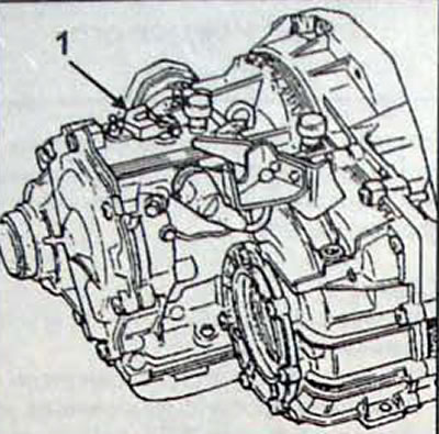


Fig. 7.8. Location of the control lever (1)
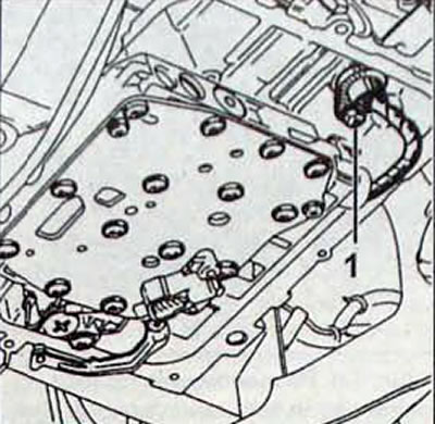
Fig. 7.8. Location of the control lever (1)


Fig. 7.9. Location of the bolt (1) securing the sealed connector
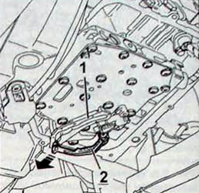
Fig. 7.9. Location of the bolt (1) securing the sealed connector


Fig. 7.10. Removing the mode switch lever:1 - mode switch lever; 2 - selector
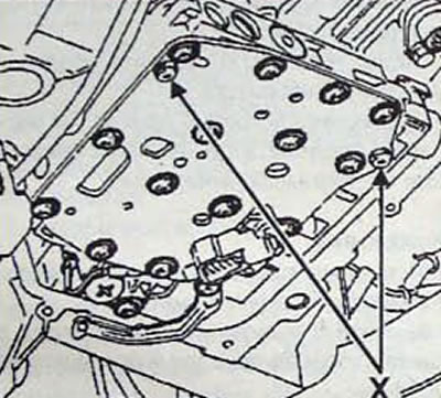
Fig. 7.10. Removing the mode switch lever:1 - mode switch lever; 2 - selector


Fig. 7.11. Location of screws (X) for fastening the end plate to the hydraulic block
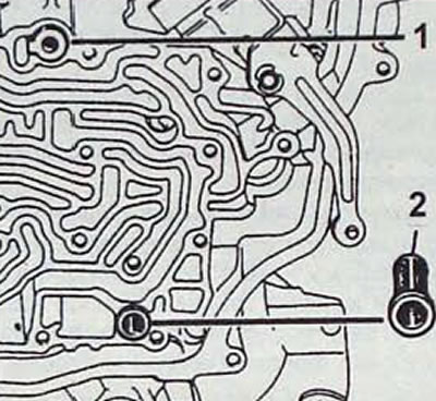
Fig. 7.11. Location of screws (X) for fastening the end plate to the hydraulic block


Fig. 7.12. Installing the hydraulic distributor: 1 - supply pipeline F1; 2 - electromagnetic valve…

Fig. 7.12. Installing the hydraulic distributor: 1 - supply pipeline F1; 2 - electromagnetic valve filter
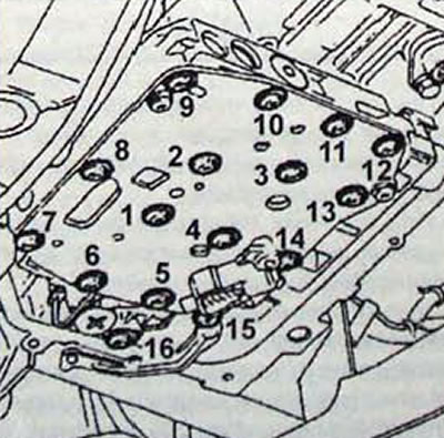

Fig. 7.13. Sequence of tightening the hydraulic unit mounting bolts
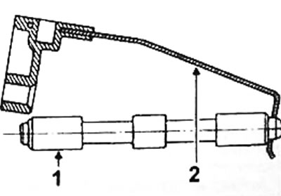
Fig. 7.13. Sequence of tightening the hydraulic unit mounting bolts


Fig. 7.14. Installation position of the control spool (1) and the linkage (2)

Fig. 7.14. Installation position of the control spool (1) and the linkage (2)

  • Make sure the supply line is installed (1, Fig. 7.14) and electromagnetic modulating valve filter
  • Install the hydraulic distributor. Screw in the 16 bolts securing the hydraulic distributor to the crankcase and tighten them in a certain sequence to the required torque
  • Install the automatic transmission mode selection control valve and the gear shift lever in place.
  • Install the sealed connector with the O-ring and secure it with the bolt.
  • Install a new filter and seal
  • Install the oil pan (check the condition of the gasket and the position of the magnetic catcher).
  • Tighten the oil pan mounting bolts to 9-11 N·m.
  • Connect the sealed connector
  • Set the mode switch.
  • Fill the transmission with transmission fluid.
This article is available on: russian, bulgarian, belarusian, ukrainian, serbian, croatian, romanian, polish, slovak, hungarian
Article has been reviewed by editor: Trofimova Anastasia
Share with friends:
Previous
Espace III: Automatic gearbox
Next

Replacing the mesh filter
Automatic transmission warning light
Checking the transmission fluid level
Transmission fluid replacement
Operation of cars with automatic transmission
Removal and installation of automatic transmission
Load Potentiometer Programming
Solenoid valves
Switch for forced engagement of 1st gear «kick-down»
Replacing drive shafts
Other articles on other Renault models

➽ Removal and installation the hydraulic distributor Renault Fluence 1 (2009-2020, petrol)
➽ Electromagnetic valves of hydraulic distributor Renault Laguna 2 (2001-2007)
➽ Removal and installation the hydraulic distributor Renault Megan 2 (2002-2009, petrol)
➽ Brake line between the hydraulic unit and the master cylinder Renault Duster 1 (2009-2017)
➽ Removal and installation the ABS hydraulic unit Renault Kangoo 1 (1997-2007)
Link to this article in different formats
Reviews and comments of visitors
No comments yet


Add two numbers 34 + 16


Renault 19 (1988-1996) 
  • General information
  • Maintenance
  • Power unit
  • Engine repair
  • Exhaust system
  • Cooling system
  • Supply system
  • Single-point injection
  • Multi-point injection
  • Diesel injection system
  • Transmission
  • Clutch
  • Car gearbox
  • Chassis, running gear
  • Car suspension
  • Steering
  • Brake system
  • Wheels and tires
  • Body and interior
  • Exterior (external elements)
  • Interior (internal elements)
  • Heating and ventilation
  • Electrical equipment
  • Equipment and devices
  • Headlights and lighting
  • Ignition system
  • Power devices
  • Electrical circuits
Espace I and II (1984-1996) 
  • General information
  • Introduction to the guide
  • Troubleshooting
  • Power unit
  • Engine repair
  • Cooling system
  • Carburetor fuel system
  • Injection fuel system
  • Diesel fuel system
  • Ignition system
  • Transmission
  • Clutch
  • Car gearbox
  • Drive shafts
  • Chassis, running gear
  • Brake system
  • Steering
  • Front suspension
  • Rear suspension
  • Body and interior
  • Exterior (external elements)
  • Interior (internal elements)
  • Doors, locks and windows
  • Electrical equipment
  • Equipment and devices
  • Electrical circuits
Espace III (1996-2002) 
  • General information
  • Introduction to the manual
  • User manual
  • Power unit
  • Petrol engines F3R
  • Petrol engines Z7X
  • Diesel engines G8T
  • Diesel engines G9T
  • Transmission
  • Clutch
  • Mechanical gearbox
  • Automatic gearbox
  • Drive shafts
  • Chassis, running gear
  • Steering
  • Front suspension
  • Rear suspension
  • Brake system
  • Body and interior
  • Exterior (external elements)
  • Interior (internal elements)
  • Doors, locks and windows
  • Heating and ventilation
  • Electrical equipment
  • Equipment and instruments
  • Power devices
  • Electrical circuits
RenaultBook.ru © 2018–2026 | Mobile version | News and articles | Sitemap: EN BG BY UA RS HR RO PL SK HU | Administration | Site search | Bookmark
Duster 1 (2009-2017) | Fluence 1 (2009-2020, petrol) | Kangoo 1 (1997-2007) | Laguna 2 (2001-2007) | Logan 1 (2004-2012, petrol) | Logan 2 (2012-2020) | Megane 1 (1995-2002) | Megan 2 (2002-2009, petrol) | Sandero 1 (2007-2012, petrol) | Scenic 1 (1996-2003) | Symbol 1 (1999-2008, petrol) | Symbol 2 (2008-2013, petrol) | Renault 19 (1988-1996) | Espace I and II (1984-1996) | Espace III (1996-2002) | Clio 1 (1990-1998) |
We want your visit to be comfortable 😌 and use cookies 🍪 to do so.