
- Different gear ratios in an automatic transmission are achieved by locking certain elements of the planetary gears (6, fig. 7.1).
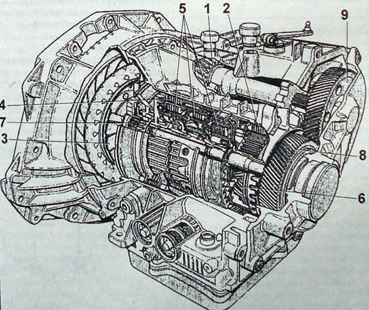
Pic. 7.1. Automatic transmission: 1 - main gear; 2 - hydraulic distributor block; 3 - torque converter; 4 - brake mechanisms; 5 - friction clutches; 6 - planetary gear; 7 - oil pump; 8 - drive gear; 9 - driven gear
- Locking is performed by the brake mechanism (4) and multi-plate friction clutches (5), working in oil. They are driven by hydraulic fluid pressure. pumped by an oil pump (7), which is part of an automatic transmission and is driven directly by the engine through a torque converter (3).
- The oil pump supplies oil through the hydraulic distributor block (2), which has valves for supplying oil under pressure to the required brake mechanisms (4) and friction clutches (5).
- main gear (1) transmits rotational motion from the automatic transmission to the drive shafts, and its ratios are part of the overall transmission ratio.
- In an automatic transmission, commands to shift gears are sent by an electronic control unit, which receives signals from sensors that monitor vehicle speed, accelerator pedal position, engine speed and selector lever position.
Torque converter
- The torque converter provides hydraulic communication between the engine and transmission. It increases torque when starting the car.
- In 3rd and 4th gears, the torque converter ensures that torque is transmitted to the gearbox without change (mechanical link) via damper hub (M. fig. 7.3), mounted on the torque converter housing (WITH).
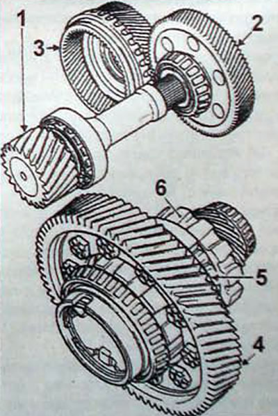
Pic. 7.2. Final drive and differential of AD8 automatic transmission: 1 - main gear; 2 - driven gear; 3 - drive gear; 4 - spur gear; 5 - differential; 6 - parking retaining ring
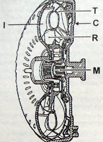
Pic. 7.3. Torque converter: I - torque converter; M - damper hub; C - torque converter housing; I - pump wheel; R - reactor; T - turbine wheel
Electrohydraulic unit
- The electrohydraulic unit consists of the following components and elements.
- Shift spool solenoid valves (EVS) when power is supplied to them, they provide hydraulic gear shifting. Solenoid valve modulator (EVM) controls the pressure in the pressure line depending on the commands received from the control unit.
- The temperature sensor continuously senses changes in transmission oil temperature to allow the system to adjust the pressure line pressure. It also warns the driver by flashing a warning light if the oil temperature is below -25°C or above 145°C.
- The sealed connector provides connection between the solenoid valves and the temperature sensor and the control unit.
Precautionary measures
- Do not use trichlorethylene or paint thinner to avoid possible splashing and contact with seals.
- Use only white spirit or degreaser to clean parts.
- To wipe parts, use only special cleaning paper intended for repair shops or blow the parts with compressed air. Rags can leave fibers in hydraulic circuits
- Thoroughly blow out all oil supply and lubrication channels with compressed air
- After cleaning, lubricate all parts with the recommended oil before installing them
- If, when disassembling the gearbox, it turns out that the oil is burnt or contaminated with particles of metal or friction linings:
- thoroughly rinse the torque converter only with recommended oil. Do not use any other liquid;
- remove and thoroughly clean the hydraulic distributor, all valves should move freely and not get stuck in any place;
- wash the oil cooler with degreasing liquid or white spirit and then blow it with compressed air.