
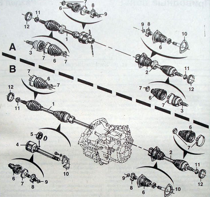
Pic. 8.1. Drive shafts:A - JC5 gearbox; B - gearbox RK1; 1 - right drive shaft; 2 - left drive shaft; 3 - constant velocity ball joint; 4 - intermediate drive shaft; 5 - intermediate shaft bearing; 6 - elastic protective cover; 7 - clamps; 8 - tripoid joint of equal angular velocities; 9 - retaining ring; 10 - clamps; 11 - nuts; 12 - ABS sensor rotor
Drive shafts are supplied as spare parts in cardboard protective packaging, which protects the elastic corrugated protective covers of CV joints from damage during transportation. It is recommended to remove these protective packaging immediately before installing the drive shaft on the vehicle. The right drive shaft of cars with the PK1 gearbox can be removed separately if the intermediate shaft remains in place, thereby eliminating the possibility of damage to the differential seal
Removal
- Remove the wheels.
- Unscrew the nut securing the tie rod end to the steering knuckle.
- Tav puller 476 press the tie rod end hinge pin out of the steering knuckle.
- Install the protective cover on the drive shaft outer joint boot.
- Remove the front floating brake caliper bracket and secure it to the suspension spring to protect the brake hose from damage.
- Release the ABS sensor wires from the mounting brackets
- Use a special device to block the hub from turning.
- Unscrew the nut securing the drive shaft to the hub.
Attention. Do not block the hub from turning. pressing the brake pedal, as this may damage or cut off the brake disc mounting bolts.
Right side of the car
Gearbox RK
- Only the outer part of the drive shaft can be removed. In this case, cut off the clamp holding the boot on the inner joint housing and disconnect the drive shaft.
Note. The hinge body does not have a stopper and can be removed without effort.
- Do not remove the rollers from the journals, since the rollers and bearing needles are matched to each other and cannot in any case be mixed up.
- If the wire shaft is removed as an assembly. unscrew the two bolts securing the locking plate of the intermediate support bearing of the drive shaft (pic. 8.4)
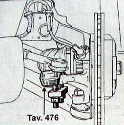
Pic. 8.2. Using the Tav puller. 476 to disconnect the tie rod end from the steering knuckle
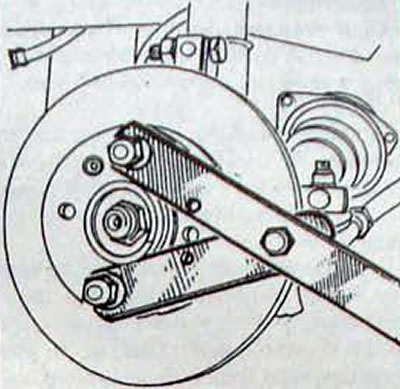
Pic. 8.3. Using a special device Rou. 604-01 for blocking the hub from turning
Pic. 8.4. Location of the bolts securing the intermediate support of the drive shaft in the support bearing of the RK1 gearbox
JC5 gearbox
- With the help of a beard V. V». 31-01, knock out the elastic pin securing the right drive shaft to the differential output shaft (pic. 8.5).
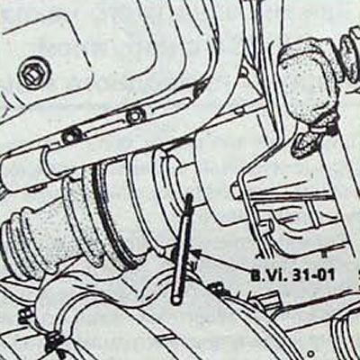
Pic. 8.5. Using the B.Vi.31-01 bit to drive out the elastic pin of the right drive shaft of the JC5 gearbox
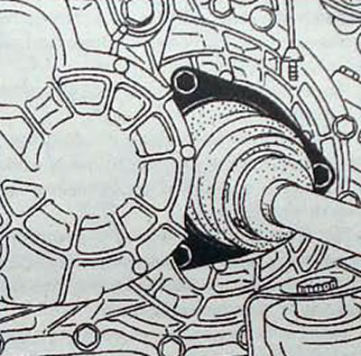
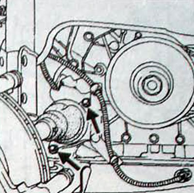
Pic. 8.6. Location of bolts securing the corrugated boot of the drive shaft to the differential flange
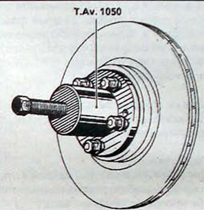
Pic. 8.7. Using the puller T. Av. 1050 for pressing the drive shaft out of the front wheel hub
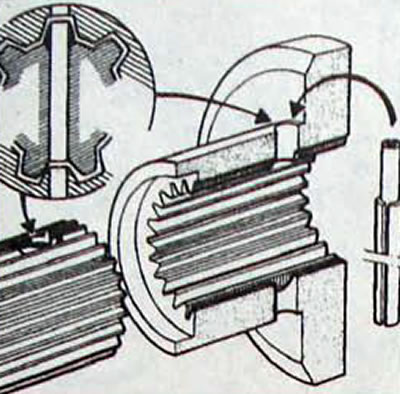
Pic. 8.8. Aligning the holes in the drive shaft and side gear to install the elastic pin
Left side of the car
- Drain the transmission oil from the gearbox.
- Remove the three bolts securing the protective corrugated cover of the inner hinge of the left drive shaft
On both sides of the car
- Unscrew the upper bolt securing the shock absorber strut to the steering knuckle and remove it. while leaving the bottom bolt in place.
- Loosen the lower bolt securing the shock absorber to the steering knuckle, but do not remove it.
- Puller T. Av. 1050-02, secured to the brake disc, press the drive shaft out of the front wheel hub.
Note. The drive shafts are glued to the hubs, so a puller must be used to remove them.
- Remove the lower bolt securing the shock absorber strut to the steering knuckle.
- Move the steering knuckle and remove the splined shank of the drive shaft outer joint from the hub.
- Using caution, remove the drive shaft from the vehicle.
Installation
Notes. Drive shafts are supplied as spare parts in protective cardboard packaging, which protects the elastic corrugated protective covers of CV joints from damage during transportation.
- Do not remove the cardboard covers until the drive shaft is installed on the vehicle.
- Do not use tools with sharp edges that could damage the bellows.
Left side of the car
- Clean the mounting location of the elastic corrugated protective cover of the CV joint on the gearbox
- Remove the protective packaging of the elastic corrugated protective cover from the gearbox side and. With the drive shaft as close to horizontal as possible, install it into the gearbox.
- Screw in the three bolts securing the protective cover holder to the gearbox and tighten them to the required torque.
Right side of the car
Gearbox RK
- Clean the bearing seat in the intermediate support.
- Check the condition of the oil seal seat on the intermediate shaft
Note. It is recommended to replace the differential flange seal whenever the drive shaft is removed.
JC gearbox
- Without removing the casing, apply MOLYKOTE BR2 grease to the splines of the drive shaft inner joint shank.
- Position the drive shaft against the side gear and slide the shaft onto the side gear splines.
- L-shaped beard B. VI. 31-01 check the position of the drive shaft.
- Beards V. Vi. 31-01, install two new elastic pins. The entrance chamfer of the hole in the side gear makes it easier to install a new elastic pin. Seal the ends of the pins with Rhodorseal 5661.
On both sides of the car
- Apply LOCTITE SCELBLOC to the hub splines.
Note. To make cleaning the splines in the hub easier, use the cut-off shank of the old drive shaft.
- Install the drive shaft into the side gear, and then insert the outer joint shaft spline into the hub.
- The splined shank of the outer joint of the drive shaft must fit freely into the front wheel hub until a thread appears for screwing on the drive shaft mounting nut. If difficulties arise, use the T. Av puller. 602.
- Further installation is carried out in the reverse order of removal.
- Press the brake pedal several times to press the brake pads against the brake rotor.
- Remove the protective packaging of the elastic corrugated protective cover from the wheel side.
- Install the wheels and lower the vehicle.