
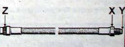
Pic. 12.26. Brake hose: X - nut, 17 Nm; Y - conical shoulder; Z - spline nut, 17 Nm
- The pipes are connected to the brake cylinders and distribution devices using cone couplings. The ends of the tubes are crimped and tapered to match the size of the tapered threaded holes in the brake cylinders or distributors. Before crimping the ends of the tubes, a lock nut is put on them, which, after screwing the cone-shaped surface into the cone base of the threaded hole, presses and seals the tube.
Removal
- Use a pipe wrench to unscrew the union nut (1, fig. 12.27) brake pipe from the brake hose end until the spring (3) will not be unloaded so much that it will be possible to remove the hose from the slotted hole (4).
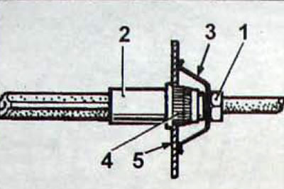
Pic. 12.27. Brake hose connection elements: 1 - union nut; 2 - brake hose; 3 - spring; 4 - slotted hole; 5 - bracket
- Unscrew the hose from the brake caliper bracket and, if necessary, remove the brake caliper bracket.
Installation
- Install the caliper bracket onto the pad guide and screw the brake hose end into the bracket, then tighten it to a torque of 14 Nm.
- The brake hoses are installed with the suspension in the following position:
- wheels are hung (suspension in place);
- the wheels are positioned to move in a straight line.
- Insert the splined end of the hose into the bracket (5). without allowing the hose to twist.
- Make sure the tip (4) the hose fits freely into the hole in the bracket, then install the spring (3) and connect the brake pipe to the hose, preventing the hose from rotating when screwing on the pipe union nut
- Tighten the union nut to the required torque.
- Remove air from the brake system.