
Removal
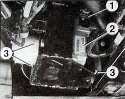
Pic. 12.33. Removing the hydraulic unit: 1 - electrical connector of the ABS control unit; 2 - ABS control unit; 3 - hydraulic unit bracket mounting bolt
- To reduce brake fluid loss, keep the brake pedal depressed.
- Disconnect the cable from the negative terminal of the battery.
- Remove the plastic protective covers.
- Unscrew the bolt and remove the rubber cushion.
- Remove the three bolts securing the ABS hydraulic unit bracket.
- Remove the bracket and tie the unit to the body so that it does not hang on the pipelines
- Disconnect the 40-pin connector from the unit.
- Use a ratchet wrench to disconnect the brake lines.
- To reduce brake fluid loss, install plugs in the fittings.
- Remove the ABS hydraulic unit and control unit.
Installation
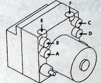
Pic. 12.34. Location of pipes on the ABS hydraulic unit: A - outlet for the pipeline to the front left brake; B - outlet for the pipeline to the rear right brake; C - outlet for the pipeline to the rear left brake; D - outlet for the pipeline to the front right brake, E - inlet for the circuit pipeline «front left - rear right brakes» from the master brake cylinder; F - inlet for circuit piping «front right - rear left brakes» from the brake master cylinder
- Installation is carried out in the reverse order of removal.
- Install the ABS hydraulic unit assembly with the control unit, ensuring the correct location of the pipes (pic. 12.34).
- Bleed the hydraulic circuit of the brake system following the required sequence of operations.
- Test the system using the G function on the XR25 handheld scan tool.
- After road test (with regulation by anti-lock braking system) check the ABS operation on the XR25.
- Confirm completion of test: G13*.