
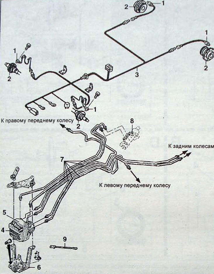
Pic. 12.29. ABS brake system components: 1 - wheel speed sensor; 2 - gear rotor; 3 - wiring harness; 4 - control unit; 5 - bracket; 6 - hydraulic tubes; 7 - main brake cylinder; 8 - connection bus «mass»
The anti-lock braking system prevents the wheels from locking during heavy braking. Thanks to this, the car remains controllable at maximum braking. ABS is ready for operation when the ignition is turned on and the warning light goes out.
Braking is most effective when the tire has maximum adhesion to the road surface. When braking, the tire slides along the surface and the peripheral speed of the wheel becomes less than the speed of the car.
The minimum slip is when the wheel is rolling freely, and the maximum when the wheel is locked. The greatest braking efficiency is achieved when the peripheral speed of the wheel is almost equal to the vehicle speed.
Description
Included in the ABS system «BOSCH 5.0» includes the following elements:
- vacuum booster with dual brake master cylinder and reservoir;
- a hydraulic control unit, including a bidirectional electric pump and a block of inlet and outlet solenoid valves;
- four assemblies of ring gears and wheel speed sensors;
- control unit combined into one unit with a hydraulic unit;
- warning lamp in the instrument cluster.
ABS «BOSCH 5.0» is a system of an additional type.
The ABS hydraulic unit is installed as an addition to the classic brake system, which includes the master cylinder and brake booster
Principle of operation
As soon as the vehicle speed reaches 5-6 km/h, the ABS performs a self-test and is ready to operate. The wheel speed is recorded by sensors installed opposite the ring gears. Information about the wheel speed is processed by the control unit and its analysis allows the system to immediately determine the beginning of blocking of any wheel. This leads to the immediate activation of the corresponding solenoid valves and a change in the pressure of the brake fluid in the working cylinder of the brake of a given wheel. The operation of the system consists of several different phases:
- phases of increasing pressure;
- pressure support phases;
- pressure decreasing phases.
- phases of increasing pressure after decreasing it.
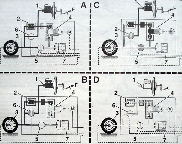
Pic. 12.30. Phases of operation of the anti-lock braking system: A - phase of increasing pressure; B - pressure support phase; C - pressure reduction phase; D - phase of increasing pressure after decreasing it; 1 - master brake cylinder; 2 - braking valve; 3 - wheel speed sensor; 4 - pump; 5 - exhaust solenoid valve; 6 - inlet solenoid valve; 7 - brake fluid pressure accumulator
Adjustment is carried out for the brakes of all wheels. The pressure in the front wheel brakes is adjusted individually in each wheel cylinder. The pressure in both rear brakes is adjusted according to the principle «select low»: «loss of traction» one wheel causes immediate adjustment of the brake pressure on the other wheel.
Pressure increase phase
During this phase, the solenoid valves and the hydraulic unit motor are de-energized. The pressure in the calipers is directly proportional to the pressure created by the force with which the driver presses the brake pedal. The braking force increases and... therefore, the wheel reduces the rotation speed and reduces its own peripheral speed relative to the speed of the car (the slip between the wheel and the road surface increases). The wheel speed is reduced to values at which traction is reduced and the wheel begins to slip. In this case, it is necessary to reduce the braking force so that the wheel increases its speed and restores traction with the road surface.
Pressure support phase
During this phase, wheel speed and acceleration increase continuously, while the intake solenoid valve breaks the connection between the master cylinder and the disc brake caliper, and the pressure in the caliper is maintained constant at the level previously achieved, regardless of the degree of pressure on the brake pedal.
Pressure reduction phase
This phase occurs only in that case. if the pressure in the pressure support phase exceeds what is currently required.
The ABS control unit receives information from the wheel speed sensor and activates the anti-lock braking system. Intake solenoid valve breaks connection» between the main brake cylinder and the disc brake caliper
At the same time, the outlet solenoid valve opens, turning on the electric motor and pumping brake fluid from the caliper into the reservoir. The pressure is reduced instantly thanks to the low pressure accumulator. The operation of the pump allows the fluid accumulated in the batteries to be pumped to the brake master cylinder.
The phase of increasing pressure after decreasing it
In this phase, the exhaust solenoid valve closes and the inlet solenoid valve opens, with the master cylinder again connected to the disc brake caliper. Hydraulic power is provided by the brake master cylinder, as well as by a constantly operating pump. This leads to an intermittent change in pressure in the caliper, which is perceived by the driver when the brake pedal is pressed hard and sharply. This is completely normal when the anti-lock braking system is operating and alerts the driver to the adjustment process.
Examination
System «EBV» (electronic brake force distribution), which is integrated into the regulation program, made it possible to eliminate the brake force regulator.
This system allows:
- increase the distribution of braking force to the rear wheels, which leads to a reduction in the thermal load on the front brake mechanisms;
- increase stability when braking in corners,
- ensure a constant distribution of braking force throughout the entire service life of the system.
If the control system fails, the ABS warning light in the instrument cluster lights up. In this case, the vehicle is braked without distributing the braking force between the front and rear wheels, i.e., if ABS is disabled, a road test is not required.