
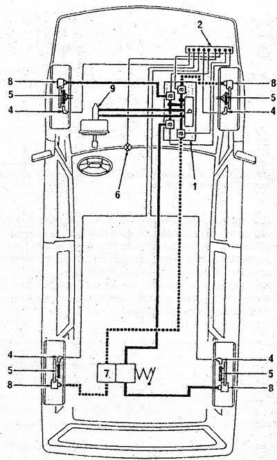
21.1 Individual components of the ABS brake system 1. Hydraulic module; 2. Computer; 4. Wheel speed sensor; 5. Toothed rim; 6. Signal lamp; 7. Pressure regulator in the brake drive system; 8. Disc brake calipers; 9. Brake master cylinder and brake booster
The main part of the system is the hydraulic pressure sensor in the system, which consists of a hydraulic module (1) with electric pump (b) and four control valves (A). Further, a computer is connected to the system with automatic recording of damage diagnostics (2), four speed sensors per wheel (4), four toothed rims (5), which are installed on the drive shafts of the front wheels and the hubs of the rear wheels, as well as a signal lamp installed on the instrument panel. Master brake cylinder and brake booster (9) assembly provides pressure to all four brake calipers (8).
The microcomputer controls the system and is located in the engine compartment. The ABS relay is also located in the engine compartment in a black box. The hydraulic module is shown in illustration 21.2. Each wheel is equipped with a speed sensor. The toothed rims in each brake disc receive the rotational speed of each wheel in time intervals and transmit the corresponding data to the control module. The toothed rims of the rear wheels are built into the hubs and cannot be separated.
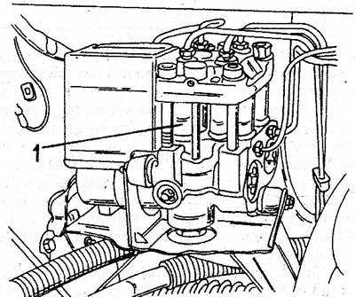
21.2 ABS hydraulic module (1) mounted on the frame cross member near the front wheel well
The signal lamp on the instrument panel indicates the functioning of the system.