
Fan thermal switch
Health check
1. Checking the health of the switch is described in Section Check of serviceability, removal and installation of the electric fan.
Removing
1. The switch is screwed into the left side of the radiator. Allow the engine to cool before removing it.
2. Disconnect the earth cable from the battery (on Scenic models, refer to Chapter Engine electrical equipment).
3. Partially drain the liquid from the cooling system so that its level drops below the switch. Alternatively, select a suitable plug and seal the opening for the switch in the radiator after it has been removed. If the second method is used, be very careful not to damage the heatsink.
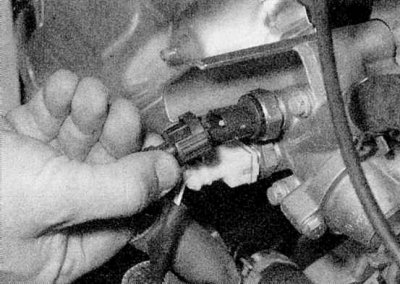
4. Separate the wiring connector from the switch.
5. Carefully unscrew the switch from the radiator and remove the O-ring (where available). If the fluid from the system has not been drained, block the opening under the switch.
Installation
1. If the switch was installed with an O-ring, replace the seal. Where an O-ring was not present, clean the switch threads and coat them with fresh sealant.
2. Install in reverse order. Tighten the switch and top up the fluid level in the cooling system.
3. Finally, start the engine and let it warm up to normal operating temperature. Make sure the fan runs for a few minutes after warming up.
Warning lamp/coolant temperature gauge sensor
Health check
1. The coolant temperature gauge/warning light sensor is installed in the thermostat housing at the left end of the cylinder head. On petrol models, this is the upper of the two sensors located on the front wall of the thermostat housing; on diesel models, the sensor is installed at the end of the housing.
2. Constant voltage to the temperature gauge is supplied from the power wire of the dashboard (through the ignition switch and fuse). The chain of connection with the mass of the pointer is closed by the sensor. The sensor contains a thermistor, an electronic component whose electrical resistance decreases when it is heated. While the engine is not warmed up, the resistance of the sensor is high and the current passing through the pointer is small, which is why the instrument needle remains in "cold" sector of the scale. As the temperature of the coolant rises and the resistance of the sensor drops, the pointer moves to the upper edge of the scale. If the sensor is defective, replace it.
3. Voltage is supplied to the coolant temperature warning lamp from the instrument panel. The lamp ground circuit is closed by the sensor. The sensor acts as a switch that operates at a certain temperature.
4. If the temperature gauge is out of order, first check the operation of other devices. If they do not work, check the power supply to the dashboard. If the instrument readings are variable, the stabilizer may be faulty and it needs to be replaced (the stabilizer is built into the printed circuit board of the instrument panel - refer to Chapter 12). If only the temperature gauge is faulty, check it as follows.
5. If after warming up the engine, the pointer remains in "cold" sector of the scale, disconnect the sensor wiring connector and ground the appropriate wire to the cylinder head. If now the arrow deviates after switching on the ignition, the sensor is defective and should be replaced. If the arrow still does not move, remove the instrument panel (Chapter Onboard electrical equipment) and check the resistance of the wiring between the sensor and the pointer, as well as the supply part of the circuit. If the circuit is continuous, the pointer itself is defective and should be replaced.
6. If the pointer stays in "hot" sector of the scale after the engine has cooled down, disconnect the sensor wiring. If now, when the ignition is turned on, the arrow returns to "cold" sector, the sensor is defective and must be replaced. If the needle still does not move, check the rest of the chain as described above.
7. Check of a chain of a control lamp is made similarly.
Removal and installation
1. On petrol models, the removal and installation of the sensor is carried out similarly to the procedures described in paragraphs Removal and Installation (FAN THERMAL SWITCH) .
2. On diesel models, refer to paragraphs Removal and Installation (FAN THERMAL SWITCH) , bearing in mind that the sensor is attached to the housing with brackets. Press the sensor into the housing, then use a small flathead screwdriver to pry out the mounting bracket and remove the sensor and O-ring. When installing, place a new O-ring on the sensor, then press the sensor into the thermostat housing and secure it in working position with a bracket.
Fuel Injection Coolant Temperature Sensor - Petrol Models
Health check
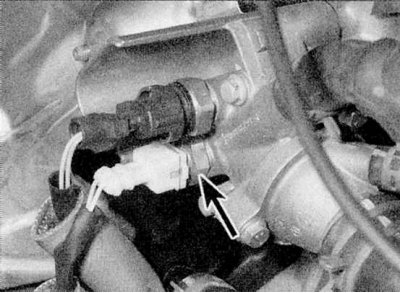
1. The fuel injection system coolant temperature sensor is located in the thermostat housing. This is the lower of the two sensors screwed into the front of the housing (refer to accompanying illustration).
2. The sensor is a thermistor. Electronic engine/fuel injection control unit (ECU) applies a certain voltage to the sensor and then, by measuring the current in the sensor circuit, determines the temperature of the engine. This information, combined with other data, is then used to adjust the duration of the injection. On some models, idle speed and/or ignition timing will also change with temperature.
Removal and installation
1. Remove and install the sensor using the information provided in the Removal and Installation paragraphs (FAN THERMAL SWITCH).