
Removing
1. Remove the battery (see chapter Engine electrical equipment).
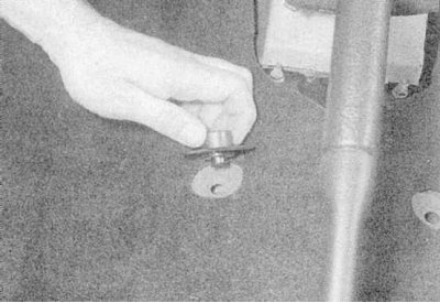
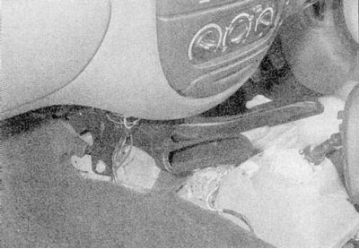
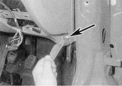
2. Remove the front seats (see Section Removal and installation of seats), then remove the spacer bushings of their mounting supports (refer to accompanying illustration).
3. Remove the steering column (see chapter Suspension and steering).
4. Remove the center console (see Section Removal and installation of the center console).
5. Acting in accordance with the instructions given in Chapter Onboard electrical equipment, remove the following components:
- a) Driver's switch panel;
- b) Instrument panel;
- c) cigarette lighter;
- d) Multifunction display;
- e) Windshield wipers.
6. Remove the heater operation control panel (see chapter Cooling, heating system).
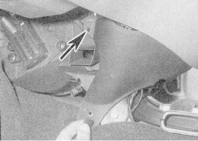
7a. Remove the bottom clips, then release the top clips.
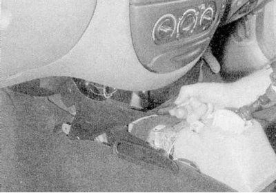
7b. Remove the center console trim from the base of the instrument panel.
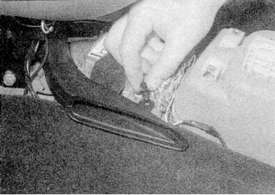
7c. Then release the latches.
7d. Remove the heater duct below (refer to illustrations).
8. Remove the sealing strip from the top edge of the engine compartment bulkhead.
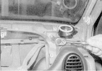
9. Turn out fixing screws, then release clamps and remove the diffuser of system of ventilation of salon, located in the basis of a windscreen.
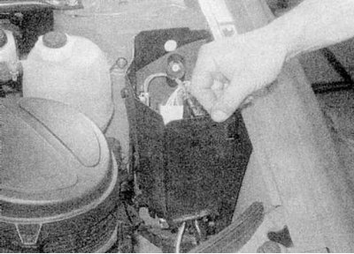
10a. Release the fuse/relay panel clips.
10b. In the left side of the engine compartment, remove the cover of the fuse/relay mounting block, then remove the front panel from the box housing of the block.
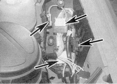
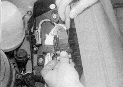
10c. Disconnect the main engine wiring harness connectors.
10d. Give fasteners (screws and clamps) and remove the front and rear sections of the left front wheel arch locker.
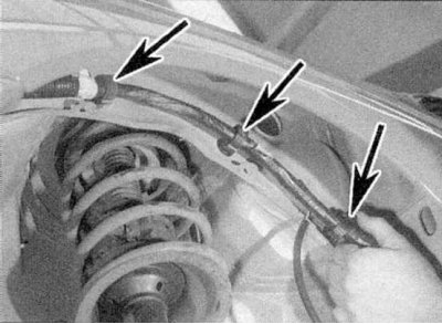
10e. Release from a wing a socket of a lamp of the lateral repeater of the index of turn.
10f. Then release its electrical wiring from the intermediate clamps so that it can be freely drawn into the vehicle interior (refer to illustrations). If you need to expand the working space, jack up the front of the car and place it on props, then remove the left front wheel.
11. On the right side of the engine compartment, release the large fuses from the mounting clips. Disconnect the electrical wiring from the heater fan electric motor and release it from the intermediate clamps so that the wires can be freely drawn into the passenger compartment.
Comment: The last condition is not mandatory for all models. In some cases, the harness is connected to the instrument panel and can be left in place.
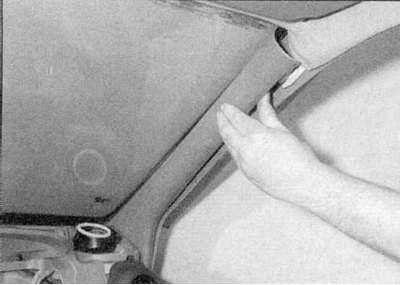
12. Separate door seal strips from A-pillar trim panels (move from top to bottom). Remove both panels (refer to accompanying illustration).
13. On Hatchback models, remove the left and right pillar trim panels (see Section Removing and installing seat belt components). On Coupe models, remove the rear seat cushion (see Section Removal and installation of seats), then remove the left and right lower sections of the seat side trim panels (see Section Removing and installing seat belt components).
14a. On all models, release the fixing screws and remove the pillar/sill trim panels of both front doors (see Section Removing and installing seat belt components).
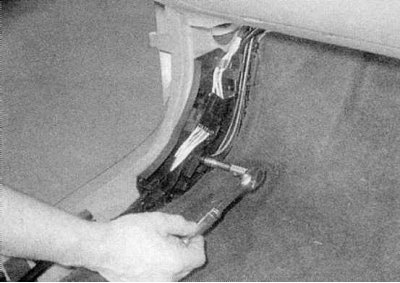
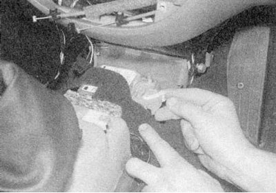
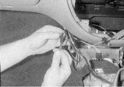
14b. Remove the screws and disconnect the ground rails from the left and right thresholds, then release from the latches and disconnect the instrument panel electrical wiring connectors (refer to illustrations).
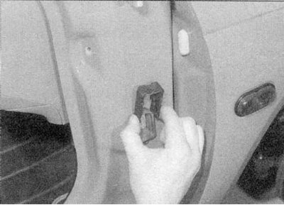
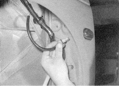
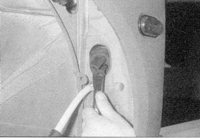
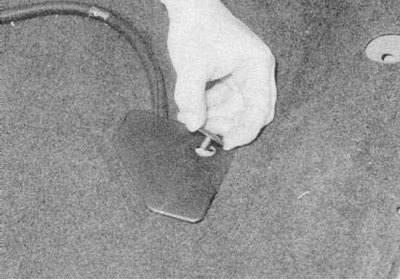
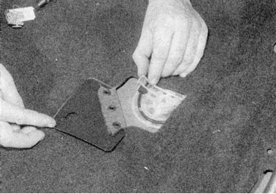
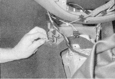
15a. Release fixing clips and disunite sockets of electroconducting of the left and right forward doors.
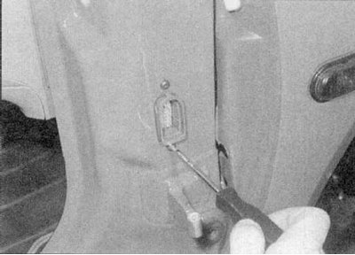
15b. Completely remove the clamps from the connectors, then release the screws and release the connectors from the racks (refer to illustrations).
16a. Referring to wiring diagrams (see Section Front seat belt pretensioning system - general information), release the clips and disconnect the electrical wiring from the SRS control unit.
16b. Release the fasteners securing the access covers to the front seat wiring harnesses.
16c. Then, release the electrical wiring of both seats from their swivel assemblies.
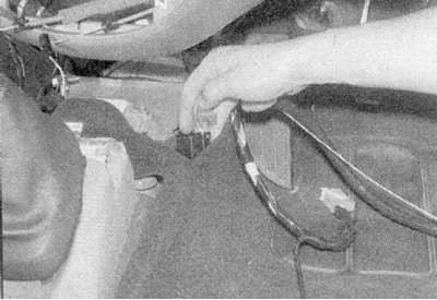
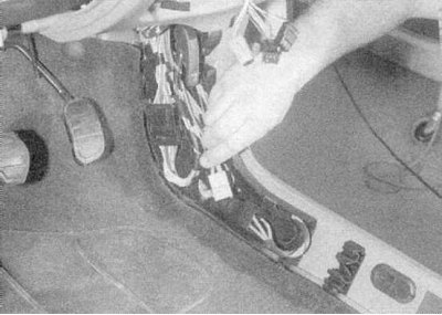
16d. Raise the carpet and release the left and right wiring harnesses from their intermediate clips so that they can be removed with the instrument panel (refer to illustrations).
17a. Turn out a bolt of fastening of the grounding bus to the left part of the central section of the instrument panel
17b. Disconnect the antenna cable (refer to illustrations).
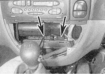
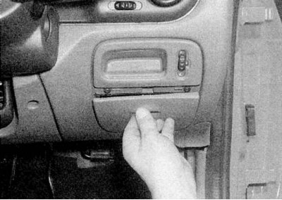
18. Turn out two screws of fastening of the panel of devices located in an aperture under installation of the control panel of functioning of a heater (refer to accompanying illustration).
19a. Carefully prying off, remove the decorative covers installed from the left and right lower corners of the instrument panel.
19b. Mounting nuts are located under the covers (refer to illustrations).
20. Give the top and bottom fixing nuts from both ends of the instrument panel (refer to accompanying illustration).
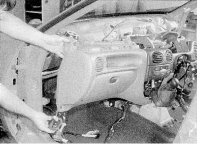
21. With the help of an assistant, carefully separate the instrument panel assembly from the bulkhead of the engine compartment (refer to accompanying illustration). As you open access, release the wiring harness bushings from the bulkhead, remembering their correct installation positions. Do not forget to release the harnesses from the intermediate clamps.
Installation
1. Installation is carried out in the reverse order. Before screwing on the fixing nuts, check the correctness of the wiring and connection of the electrical wiring, as well as the reliability of fastening of its contact connectors. Make sure that the bulkhead is seated through the bushings of all harnesses. In conclusion, do not forget to connect the battery and check the correct functioning of the electrical equipment.