
- A) Special lock for the camshaft pulley and fuel pump drive gear Mot. 854
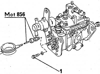
- b) Special puller for fuel pump drive gear Mot. 1053
- With) Micrometer holder and injection timing micrometer Mot. 856.
- d) Crankshaft setting pin in V MT Mot. 861. It can be replaced by a punch with a diameter of 8 mm.
2. Before removing the fuel pump mount and the camshaft drive cover, perform the following work:
3. Disconnect the negative cable from the battery. Keep your radio code handy (if installed).
4. Remove the shield and top tube of the cross member.
5. Partially detach the radiator and tip it over to expose the camshaft drive cover.
6. Position the front of the vehicle on a lift and remove the power steering pump belt, alternator belt, and water pump belt.
7. Disconnect the cable shield from the camshaft drive cover and remove the cover. This will release the fuel pump drive mechanism. Cover the generator with a thick layer of dense cloth to protect it from diesel fuel.
8. Disconnect the connections indicated by the arrows (see illustration). The two lower arrows show where the hose needs to be clamped. After applying the alignment mark of the spring clip (1) Disconnect the throttle cable, remove the locking cable and fast idle cable, disconnect the fuel lines from the high pressure fuel pump and remove the injectors.
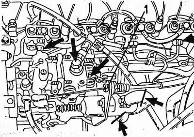
17.8 Remove the connections indicated by the arrows from the pump. Both bottom arrows indicate hose connections
9. Turn the engine so that both sprockets (camshaft and fuel pump) installed as shown in illustration 20.37 from Section 2. In the figure, the toothed drive belt is removed, however, the alignment marks are clearly visible.
10. When performing temporary installations of the camshaft drive cover, it is necessary to see the installation marks through the viewing windows. Once again check the alignment from this position, turn the crankshaft back exactly three teeth of the drive belt. In this position, insert into the engine or locking mechanisms (see illustration), or precisely mark the position of the sprockets so that they can be installed as before.
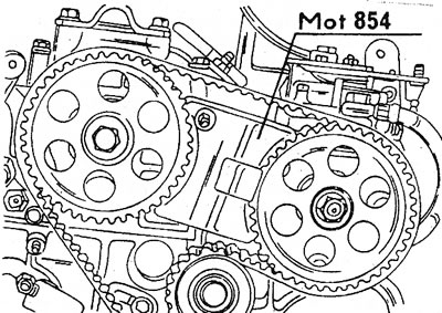
17.10 Insert a locking tool between both sprockets to prevent them from turning
11. Loosen the pump shaft nut and slide it towards the end of the shaft. If a locking mechanism is used, the engine will not be able to turn over. Otherwise, insert a punch through one of the holes in the sprocket (in the cylinder head), to prevent crankshaft rotation.
12. Using a puller, remove the drive gear from the pump (see illustration). Do not use a mallet to remove the gear. The grips of the puller are installed in the holes of the gear, and do not cling to its teeth. Because the gear is made of brittle material, the teeth can break easily.
17.12 Special puller for fuel pump drive gear
13. Remove the protective cover under the fuel pump and the rear support of the pump. Then remove the remaining pump mounting bolts. Use a bent box wrench to remove the lower pump nut.
14. Carefully remove the pump. Make sure that the locking key does not fall out of the pump shaft. Install the pump as described above and adjust provided you have a micrometer. Adjust very carefully.
15. To install a micrometer with a dial, screw on the plug (1) and slide the micrometer into the sleeve (see illustration).
17.15 Assembly and installation of a micrometer with a dial. Stub (1) must be turned out beforehand
16. Screw two nuts onto the threads of the pump shaft and lock them together.
17. Loosen the contact screw (1) (see illustration), move the lever back a little and turn the fork head a quarter of a turn.
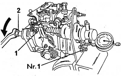
17.17 Installing the fuel pump. Numerical designations are described in the text
18. Turn the pump shaft in the direction indicated by the arrow in illustration 17.17 (put the ring wrench on the mounted nut «2»), to find the BDC of the piston. In this position, slide the micrometer back about half way through the measuring finger and set it to «zero».
19. Turn the pump shaft further in the normal direction until the keyway of the shaft is in the same plane with the threaded connections of the fuel line of the first cylinder, as shown in illustration 17.17. Loosen both screwed nuts again.
20. Insert the key into the pump shaft and slide the drive gear onto the shaft. Install the pump in the prescribed position and secure with nuts and washers to the mounting flange. Tighten the nut with your fingers.
21. Tighten the shaft nut with a tightening force of 50 Nm and remove the blocking device shown in illustration 17.10. If the locking mechanism is not used, lock the drive gear.
22. Turn the crankshaft in the normal direction and block in this position, as shown in illustration 20.33 from Section 2 (see also the description of the installation of a toothed drive belt). Illustration 17.22 shows where the crankshaft stop pin is installed in relation to the installed micrometer.
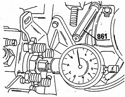
17.22 Dial micrometer and stop pins (861) installed in the fuel pump and, accordingly, in the cylinder block
23. Unscrew the fuel pump until a reading of 0.70 mm appears (tolerance±0.02 mm). Tighten the pump mount in this position.
24. Rotate the crankshaft one and 3/4 turns in the normal direction of travel (remove the locking pins) and make sure the micrometer shows «zero», if the pump piston is at BDC. Then set the crankshaft back to TDC and push in the locking pins (see also illustration 17.22).
25. Check that the micrometer reads 0.68-0.72 mm and that the alignment marks on the pump drive gear and on the camshaft sprocket are located as shown in illustration 20.37 from Section 2 or temporarily install the camshaft drive cover to view the alignment marks through the viewing windows. Remove the micrometer from the back of the pump and screw in the plug with a new gasket.
26. Press the cold starter lever and lock the clip in its original position if the lever is against the fork head.
27. Connect a back support to the fuel pump and to a head of the block of cylinders. Tighten the fastener evenly.
28. Perform the rest of the work in reverse order. Pay attention to the differences in hollow bolts. The hollow bolt of the fuel outlet pipe has a channel of a certain diameter and a filter. This bolt is screwed approximately in the middle of the pump.
29. Fast idle adjustment is made as described in next chapter.
30. To remove air from the fuel system, remove the union nuts of the high pressure fuel lines from the pump. If the fuel comes out of the threads of the union nuts without bubbles, the system does not contain air. Then tighten the union nuts with a tightening torque of 20 Nm.