



Note: Installation will require a new cylinder head gasket, valve cover gasket, and exhaust outlet pipe O-ring.
Removal
1. Remove the battery as described in Section 5A.
2. Remove the hood as described in Section 11.
3. Drain the cooling system, including the cylinder block, as described in Section 1A or 1B. The drain plug in the block is located on the right rear wall of the engine.
4. Drain the engine oil as described in Section 1.
5. Remove the air cleaner assembly according to the corresponding Part Section 4.
6. Remove the toothed drive belt, see Chapter 6.
7. Disconnect the exhaust outlet pipe from the manifold, referring to the relevant Section Section 4.
8. Disconnect the crankcase ventilation hoses from the valve cover (see illustration).
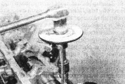
12.8. Crankcase ventilation hoses on the valve cover - F7P engine (with 16 valves).
9. Remove the distributor cap and spark plugs, following the relevant Sections 5 and 1, if necessary.
10. Disconnect the gas pedal cable and move it to the side.
11. Disconnect the wiring harness going to the engine and remove the ignition/fuel injection system processor unit, referring to the appropriate Section Section 4.
12. Unscrew the generator bracket from the intake manifold.
13. Unscrew the starter bracket from the exhaust manifold.
14. Unscrew the exhaust manifold heat shield.
15. Remove the radiator and fan as described in Section 3.
16. Unscrew the two support posts from the base of the intake manifold.
17. Unscrew the spark plug housing from the top of the valve cover (see illustration).
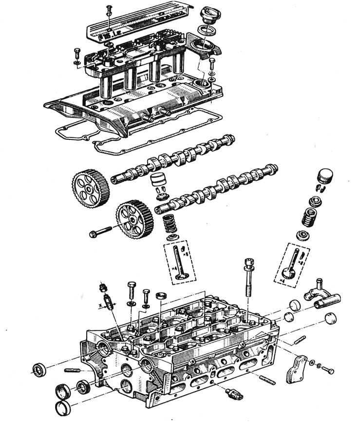
12.17. Cylinder head - F7P engine (with 16 valves).
18. Unscrew the valve cover from the cylinder head and remove the two gaskets.
19. Using a T55 socket wrench, gradually loosen the cylinder head mounting bolts, turning them half a turn at a time in the reverse order to that shown in Illustration 11.29.
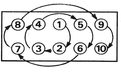
11.29. Cylinder Head Bolt Tightening Sequence - All F-Series Engines.
20. Lift the head from the cylinder block. If this fails, hit the head with a mallet.
Inspection
21. The mating surfaces of the cylinder head and block must be completely clean. Using a scraper, remove all traces of gasket and carbon deposits and clean the tops of the pistons. Work especially carefully with the aluminum cylinder head, as the soft metal can be easily damaged. Also, be careful not to let dirt get into the oil and water passages - this is especially important for the lubrication chain, as carbon deposits can block the oil supply to the camshaft and crankshaft bearings or rocker arms. Use masking tape and paper to seal the water and oil passages and bolt holes in the cylinder block. Clean the piston heads in a similar manner.
22. Check the block and head for nicks, deep scratches and other damage. If there are small scratches, they can be carefully removed with a file. More serious damage can be repaired by resharpening, but this work should be entrusted to a specialist.
23. Using a ruler placed on its edge, check the warpage of the cylinder head. If necessary, see Part F of this Section.
24. Clean all bolt holes in the block. Make sure there is no oil left in them, otherwise there is a risk that the block may crack under hydraulic pressure when tightening the bolts.
25. Inspect the bolt threads and the threads in the cylinder block for damage. If necessary, use a tap of the appropriate size to renew the threads in the block and use a thread-cutting die to clean the threads on the bolts. It is recommended to replace the bolts after each removal.
Installation
26. Check that the mating surfaces of the cylinder block and head are spotlessly clean, that the threads of the mounting bolts are clean and dry and that they screw in easily.
27. Make sure that piston No. 1 is at TDC and the timing mark on the camshaft sprocket is aligned with the mark on the shield.
Caution: If the camshafts are not positioned correctly, the valves may hit the pistons.
28. Install the new head gasket onto the cylinder block, positioning it on the pins. Make sure it is oriented correctly.
29. Lower the cylinder head, placing it on the pins.
30. Lightly lubricate the cylinder head mounting bolts with oil. Insert the bolts and tighten them by hand.
31. In the sequence shown (see illustration 11.29) tighten the bolts to the torque specified in Specifications for Stage 1. In the same sequence, tighten the bolts to the specified Specifications for Stage 2 angle.
32. Wait three minutes, then gradually loosen all the bolts completely in the reverse order of tightening them. These are Stage 3 and Stage 4.
33. Again, tighten the bolts in the sequence shown to the torque specified in Specifications for Stage 5.
34. Finally, tighten each bolt to the specified value Specifications for Stage 6 angle. No re-tightening is required after the engine has warmed up.
35. Install the valve cover together with new gaskets and tighten the bolts to the specified torque Specifications.
36. Install the spark plug housing onto the valve cover and tighten the bolts.
37. Secure the support struts to the intake manifold.
38. Install the radiator as described in Section 3, but do not fill the cooling system at this stage.
39. Attach the starter bracket to the exhaust manifold.
40. Install the exhaust manifold heat shield.
41. Install the generator bracket.
42. Install the engine wiring harness and the fuel injection/ignition system processor unit.
43. Connect the accelerator pedal cable, referring to the relevant Section Section 4.
44. Install the distributor cap and spark plugs, referring to the appropriate Part of Sections 5 and 1.
45. Connect the crankcase ventilation hoses.
46. Connect the exhaust outlet pipe using a new O-ring.
47. Install the toothed drive belt, see Chapter 6.
(Original publication on the website RENAULTBOOK.ru)
48. Install the air cleaner assembly according to the relevant Section Section 4.
49. Fill the engine with oil as described in Section 1.
50. Fill the cooling system as described in Section 1.
51. Install the hood as described in Section 11.
52. Install the battery as described in Section 5A.