



Note: A new valve cover gasket will be required during installation.
Removal
1. Remove the toothed drive belt as described in Chapter 5.
2. Disconnect the gas pedal cable and move it to the side, following the relevant Section Section 4.
3. Unscrew the nuts from the valve cover and remove the cover from the engine. Remove the gasket.
4. Disconnect the high tension wires and remove the distributor cap and rotor as described in Section 5B or 5C. Remove the distributor rotor shield.
5. Remove the camshaft sprocket, see Chapter 7.
6. Unscrew and remove the support shield from the cylinder head.
7. Using a micrometer, measure the axial clearance of the camshaft and compare it with the data in Specifications. In this way, the degree of wear of the axial pressure surfaces can be determined.
8. Mark the camshaft bearing caps so that they can be installed in their original location.
9. Gradually loosen the cover mounting bolts until the valve spring pressure is relieved. Remove the bolts and bearing caps (see illustrations).
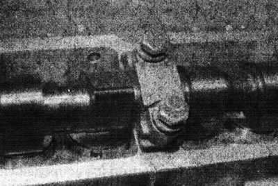
9.9a. Camshaft bearing cap and mounting bolts - F3P engine.
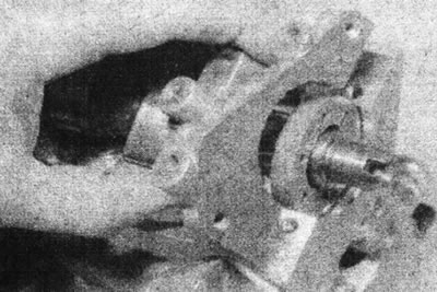
9.9b. Remove the camshaft bearing cap (from the flywheel side) - F3P engine.
(Original version on our portal renaultbook)
10. Note the position of the working surfaces of the cams. The valve cams of cylinder #1 will be facing upwards. Lift the camshaft together with the seals (see illustration).
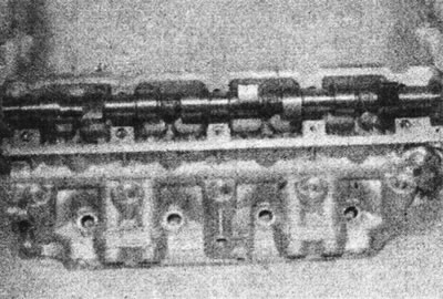
9.10 Lift the camshaft out of the cylinder head - F3P engine.
11. Remove the valve lifters together with the washers (see illustration).
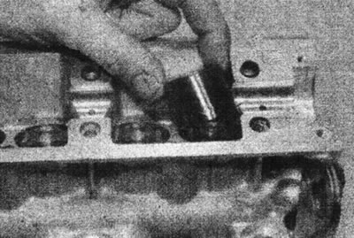
9.11 Remove the valve lifter - F3P engine.
Place them in a box, or on a piece of cardboard, divided into eight parts so that the pushers can be installed in their original place. Record the thickness of the adjusting washers - this information will be needed later when adjusting the valve clearances.
Inspection
12. Inspect the working surfaces of the camshaft bearings, the working surfaces of the cams and the eccentric screw of the fuel pump for worn areas and scratches. Replace the camshaft if such damage is found.
13. Replace the seals on the ends of the camshaft after each removal. On some models, the distributor rotor is glued to the end of the camshaft and will break during removal, while on other models it can be removed without damage. Lubricate the sealing lips of the new oil seals and place the camshaft so that it does not rest on the oil seals.
14. Inspect the working surfaces of the camshaft bearings in the cylinder head and covers. If there are deep scratches or other damage, the cylinder head must be replaced.
15. Inspect the tappets and adjusting washers for scratches, corrosion and worn areas. Replace them as needed.
Installation
16. Lubricate the valve lifters and install them in their places in the head. Install washers of the correct thickness, marked side down, onto the tappets.
17. Lubricate the camshaft bearings. Place the camshaft with seals on the cylinder head. The seals must be positioned so that they are flush with the cylinder head mounting surfaces. The working surfaces of the cams must be positioned as marked before removal (item 10).
Caution: If the cam lobe surfaces are not positioned correctly, the valves may hit the pistons when the bearing cap is tightened.
18. Install the camshaft bearing caps in their places. Apply a small amount of sealant to the end caps.
19. Apply sealant to the threads of the cover mounting bolts. Install the bolts and gradually tighten them to the torque specified in the Specifications.
20. If a new camshaft has been installed, measure the end play with a micrometer and ensure it complies with the specifications.
21. Install the support plate into the cylinder head.
22. Install the camshaft sprocket, see Chapter 7.
23. Install the toothed drive belt, see Chapter 5.
24. Check and, if necessary, adjust the valve clearances as described in Chapter 4.
25. Install the valve cover with a new gasket and tighten the nut.
26. Connect the accelerator pedal cable and adjust it as described in the relevant Section Section 4.
27. Install the runner shield, runner and distributor cap as described in Section 5B or 5C.
28. Connect the high voltage wires.