



Contents: Removal the power unit 🠛 Installation of the power unit 🠛 Tightening torques for threaded…🠛
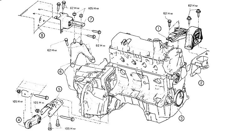
Engine K7M: 1. Cylinder head mounting support. 2. Front side member. 3. Engine with gearbox assembly. 4. Engine thrust rod. 5. Engine thrust rod support. 6. Gearbox support. 7. Gearbox elastic support on the body. 8. Front side member.
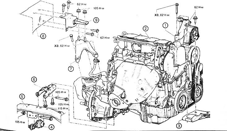
Engine K4M: 1. Right engine mounting support. 2. Engine with gearbox assembly. 3. Front side member. 4. Engine reaction thrust. 5. Front subframe. 6. Engine reaction thrust support. 7. Gearbox support. 8. Front side member. 9. Elastic support of gearbox on body.
Attention:
- Use protective gloves during work.
- To avoid refrigerant leaks from the air conditioning system, be careful not to damage the pipes (do not deform, twist, etc.). To prevent atmospheric moisture from entering the air conditioning system, it is necessary to seal all openings in the refrigerant circuit in a timely manner.
Removal the power unit
Caution: To prevent the vehicle from falling off the lift, tie it to the lift with safety straps.
1. Place the vehicle on a two-post lift.
2. Loosen the mounting bolts and remove the engine protective pan.
3. If necessary, drain the engine oil from the engine.
4. Drain the transmission oil from the gearbox.
5. Drain the coolant from the cooling system.
6. Using a special station, drain the refrigerant from the air conditioning system circuit.
7. Remove the battery.
8. Remove the engine air filter unit.
9. Remove the front wheels from the vehicle.
10. Remove the front mudguards.
11. Remove the engine thrust:
- Unscrew the engine torque rod bolt from the subframe.
- Unscrew the engine thrust bolt from the support.
- Remove the engine thrust rod.
- Loosen the mounting bolts and remove the engine thrust support.
12. Remove the front left and right drive shafts.
13. Remove the front subframe.
14. Unscrew the refrigerant pipe bracket bolts from the air conditioner compressor.
15. Drain the power steering fluid.
16. Remove the power steering pump.
17. Remove the high pressure line from the steering gear.
18. Remove the low pressure line from the steering gear.
19. Seal all open holes with plugs.
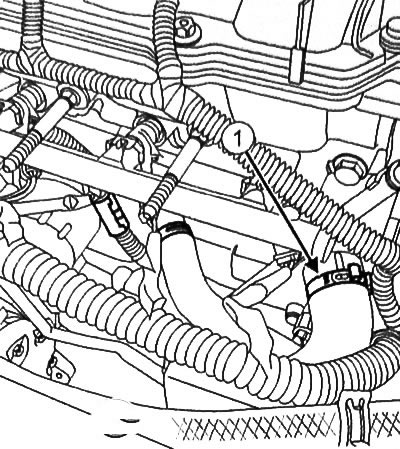
20. Engine K4M (16 valves): Using hose clamp pliers (Mot. 1448), disconnect the hose clamp (1) on the coolant inlet pipe.
21. Using hose clamp pliers (Mot. 1448), disconnect the clamp (1) from the upper radiator hose on the cooling system chamber. Disconnect the upper radiator hose from the cooling system chamber.
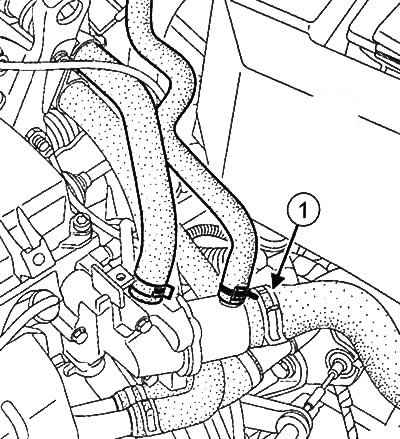
Engine K7M(8 valves)
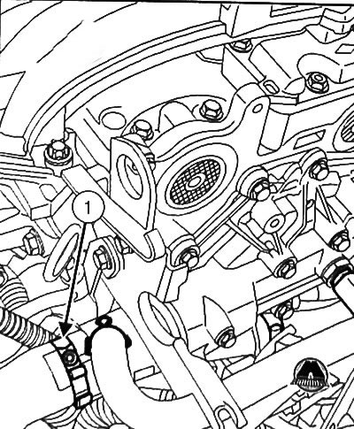
Engine K4M(16 valves)
22. Disconnect the hoses (2) from the heater core using special pliers for hose clamps (Mot. 1202-01) or (Mot. I202-02).
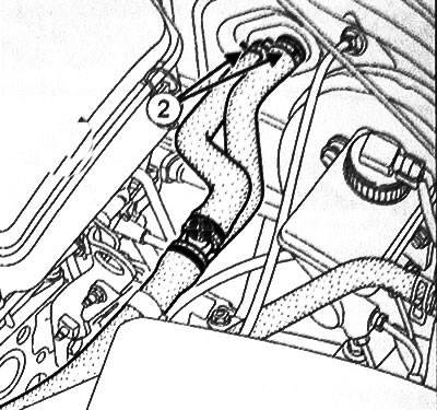
Engine K7M(8 valves)
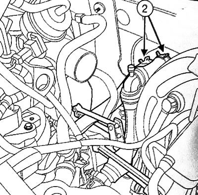
Engine K4M(16 valves)
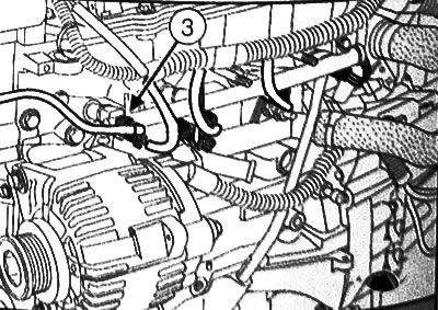
23. Disconnect the fuel supply line (3) from the fuel rail.
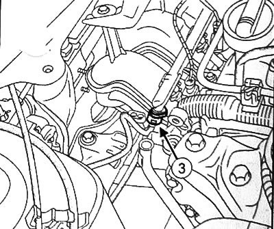
Engine K7M(8 valves)
Engine K4M(16 valves)
Attention:
- When working with components of the power supply system, smoking or using open flames in the workplace is prohibited.
- Be careful as fuel may leak when disconnecting the connector.
24. Seal the fuel supply line and fuel rail with plugs.
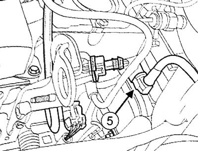
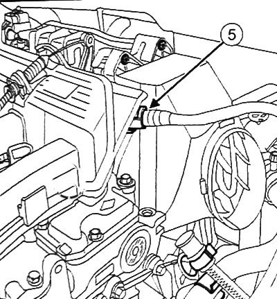
25. Disconnect the brake booster vacuum line connector (5) from the intake manifold.
Engine K7M (8 valves)
Engine K4M(16 valves)
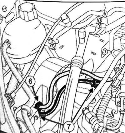
26. Disconnect the fuel vapor recirculation pipe (6) and the fuel vapor condensation wire (7).
Engine K7M (8 valves)
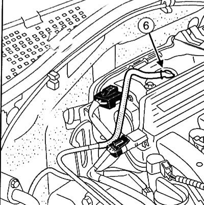
Engine K4M(16 valves)
27. Disconnect the fuel vapor absorber pipe (8), the solenoid valve connector (9) and the connector (10) of the refrigerant pressure sensor in the air conditioning system circuit.
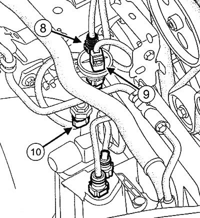
28. Unhook the wiring and put it aside.
29. Disconnect the radiator fan resistor connector (13) and the radiator fan connector (14).
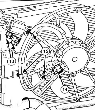
30. Disconnect the wiring from the holders (15).
31.Return the nut securing the ground busbar to the body.
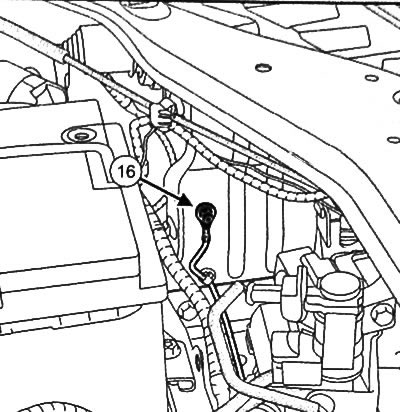
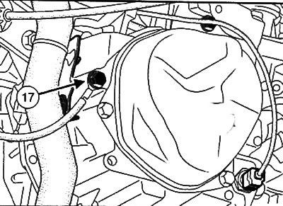
32. Loosen the ground bus bolt (17) from the manual transmission.
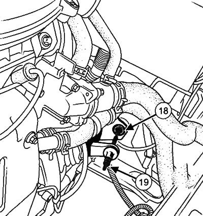
33. Remove the clutch drive cable from the thrust sleeve (18) and from the clutch release fork (19).
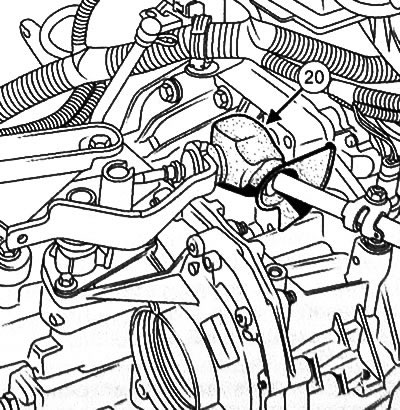
34. Remove the rubber protection (20) from the gear shift lever.
35. Unscrew the mounting bolt (21) from the gear shift lever fork.
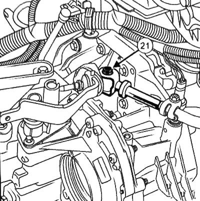
Note: The rod is connected using a spacer. Make sure not to loosen the spacer when removing the bolt (21).
36. Unscrew the nut from the gearbox connecting rod.
37. Move the gear shift drive to the side.
38. Unscrew the nut (22).
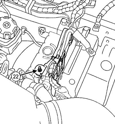
39. Disconnect the engine control unit connectors (23).
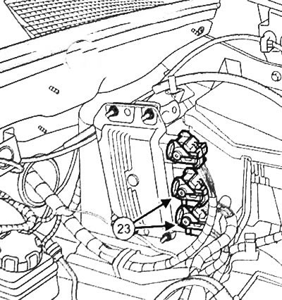
40. Remove the engine compartment junction block cover.
41. Disconnect the relay and fuse holder from the supports in the engine compartment relay and fuse box housing.
42. Place the wiring, fuses and relays on the engine.
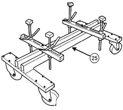
43. Support the engine with the gearbox assembly in the places indicated in the figure (24) using the support stand (Mot. 1390) (25).
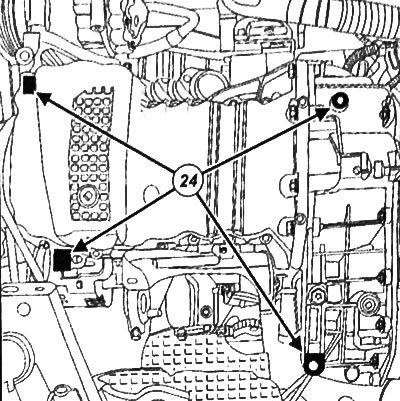
Note: Mark the position of the mounting supports on the engine.
44. Remove the right engine mounting support.
45. Remove the left engine mounting support.
Note: Make sure that the engine and gearbox do not interfere with the body.
46. Raise the car with a lift to remove the engine and gearbox from the car.
Installation of the power unit
Attention:
- To prevent leaks, make sure that the gasket and the contact surfaces of the pipes are in good condition. The contact surfaces must be clean and free of scratches.
- Plugs should be removed from any component openings immediately before the component is installed. In addition, new parts should be removed from their packaging immediately before installation.
Installation is carried out in the reverse order of removal, observing the required tightening torques
Fill the power steering circuit.
Fill and bleed the engine cooling system.
Fill the gearbox with transmission oil.
If necessary, add engine oil.
Using a special station, fill the air conditioning system.
Check for leaks in various systems.
Tightening torques for threaded connections
| Threaded connections | Tightening torque |
| Shift Lever Fork Mounting Bolt | 27.5 Nm |
| Bolt for fastening the ground bus to the gearbox | 21 Nm |
(This note was copied from the resource: renaultbook)