
Renault 19 rear suspension elements with four torsion bars
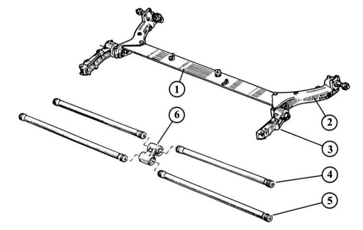
1 - V-profile transverse beam; 2 - trailing arm suspension (welded to cross beam); 3 - fastening of the longitudinal suspension arm; 4 - transverse stabilizer; 5 - torsion bar; 6 - support for torsion bars and transverse stabilizers.
The figure shows the elements of the rear suspension with a conical tube. It also shows the mount of the anti-roll bar
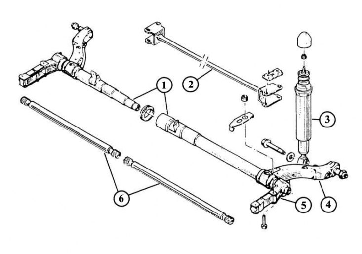
1 - engaging axle shafts; 2 - anti-roll bar; 3 - shock absorber; 4 - longitudinal suspension arm; 5 - fastening of the longitudinal suspension arm; 6 - torsion springs.
If, when measuring the position of the rear wheel, a too large deviation from the specified value was recorded, then it is necessary to completely replace the rear axle. Nothing to weld or straighten is unacceptable. Replacing torsion bars requires extensive knowledge, skills and, above all, special tools. The same applies to replacing hinges. For these reasons, we have refrained from describing these types of work.
Removing shock absorbers
1. In the trunk, remove the shock absorber upper mount cover.
2. Loosen the top nut.
3. Remove the individual elements and mark the order in which they are removed for reassembly.
4. Raise the car from behind and fix.
5. Loosen the lower shock absorber mount and remove the bolt.
6. Remove shock absorber.
7. Compress and decompress the new shock absorber several times before installation. Thus, the oil accumulated during storage in one place will be evenly distributed and the shock absorber will be ready for use.
8. Lubricate the shock mount with MoS22.
9. Install damper, threaded connections - on top with new self-locking nut - do not fully tighten yet.
10. Lower the car.
11. Tighten the bottom fastener to 60 N.m.
12. Tighten the top mount to 20 N.m.
Removing the cross stabilizer
1. Raise the machine so that the wheels hang freely and secure.
2. Turn off on the right and at the left on a trailing arm of a suspension bracket carving connections of the anti-roll bar.
3. Remove the parking brake cable guides.
4. Remove the anti-roll bar.
5. When installing, tighten the fastening bolts to 50 Nm.
Removing the wheel bearing
Both figures depict elements of the rear bearing
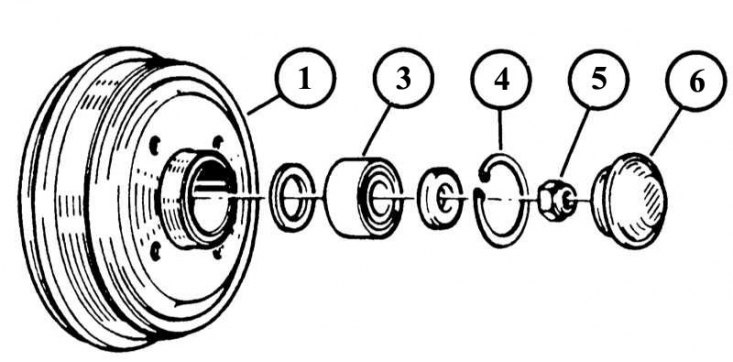 | 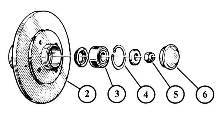 |
1 - brake drum; 2 - brake disc; 3 - wheel bearing; 4 - persistent safety ring; 5 - wheel hub nut; 6 - hub cover.
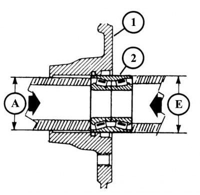
The sectional drawing shows how to press in and out a wheel bearing. The diameter of the pipe must be A = 49 mm for pressing out, for pressing E = 51 mm.
1. Loosen the wheel bolts and raise the vehicle so that the wheel hangs freely.
2. Disassemble the brake drum or, respectively, the disc brake mechanism.
3. Remove the safety stop ring with pliers from the hole in the hub of the brake drum or, respectively, the brake disc.
4. Place the brake drum or respectively the brake disc on a board or clamp it in a vise.
5. Press the wheel bearing out of the hub bore with a suitable short piece of pipe.
6. Clean the wheel hub and press in or press in the new bearing as far as it will go.
7. Put on a new thrust ring.
8. Fit the brake drum or, respectively, the brake disc onto the axle. Before doing this, lubricate the axle with lithium grease (for example, LM-320 from Liqui Moly).
9. Tighten the new self-locking hub nut, and after the car is lowered, tighten it to 160 N.m.
10. The wheel bearings do not need to be adjusted, the rotating rings, hub and axle are made with such small tolerances that after tightening the nut they are installed with the prescribed clearance in the bearing for the wheel (axial clearance max. 0.03 mm).
11. After installing the hub cover, install the brake elements in their original position.
12. Adjust the parking brake if necessary.