
Sectional front view of the front suspension
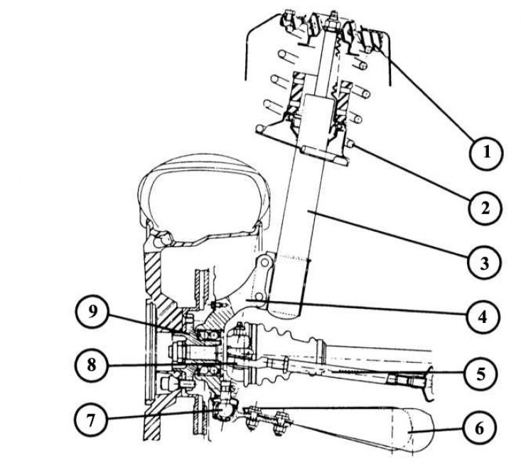
1 - upper mount of the shock absorber strut; 2 - helical spring; 3 - shock absorber assembly; 4 - steering swivel support; 5 - thrust of the steering trapezoid with a sealing cuff; 6 - transverse lever of independent suspension; 7 - ball joint of the transverse lever; 8 - the tip of the transverse steering rod; 9 - wheel hub.
Many front suspension units can be disassembled and repaired independently. However, for some jobs it is necessary to use devices that are only available in a car repair shop.
Damaged suspension elements cannot be straightened out on their own, but they simply need to be replaced.
1. With the machine standing on the ground, unscrew the nuts securing the stabilizer from the transverse suspension arm to the left and right.
2. Raise the front of the machine and secure, if necessary, remove the wheels.
3. Remove the front exhaust pipe (trousers) muffler exhaust manifold.
4. Remove the control rod by loosening the bolt from the gear lever.
5. Before that, mark the position of the control rod relative to the gearshift lever, otherwise you will have to adjust the gearshift device.
6. Loosen both support brackets of the holder on the longitudinal beam of the auxiliary frame.
7. Remove the anti-roll bar and disassemble the rubber support.
8. Lubricate the rubber support with MoS2 before installing it.
9. Install the anti-roll bar.
10. First tighten all fasteners by hand.
11. Install the exhaust pipe.
12. Install the control rod on the gear lever and - if its position was not marked during disassembly - adjust if necessary.
13. Lower the car and tighten all fasteners to 35 N.m.
Removing the wishbone independent suspension
1. With the machine standing on the ground, unscrew the nuts securing the stabilizer from the transverse suspension arm to the left and right.
2. Raise the front of the vehicle, secure and remove the relevant wheel.
3. Tilt the anti-roll bar down.
4. Remove the transverse arm ball joint retaining bolt from the steering pivot.
5. Press the spherical head out of the steering pivot (puller if necessary).
6. Remove the 2 bolts and nuts from the engine sub frame (mark the removal sequence!).
7. Remove the transverse arm from the holder axle.
8. Always use new self-locking nuts when installing.
9. When bushings are worn (silent blocks) they need to be replaced (in a car repair shop).
10. A deformed transverse arm must be completely replaced, as it cannot be straightened.
11. Insert the axle bolt into the control arm threaded first.
12. Tighten the bolt nut to 75 N.m. At the same time, hold the bolt with a wrench on the reverse side and tighten the nut.
13. Tighten the ball joint on the steering pivot bearing to 55 N.m.
14. Install the anti-roll bar.
15. Lower the car.
16. Check the wheel alignment and adjust if necessary.
Removing the shock absorber strut
1. Loosen the upper strut mount (2 bolts). For ease of reassembly, mark the position of the unit's fasteners in the mounting holes. The rear holes are attachment points for vehicles with power steering, the front holes are for vehicles without power steering.
2. Raise the vehicle, secure and remove the wheel or wheels respectively.
3. To protect the outer pivot seal, insert a wooden wedge between the seal and the lower end of the shock mount.
4. Turn off both bolts of fastening of an amortization rack from a steering rotary support (mark the position of the fastener!).
5. Lower the steering pivot down until the shock absorber strut is released. At the same time, tilt the swivel bearing exactly as much as necessary so as not to damage the constant velocity joints (CV joints).
6. To protect the cardan joints of the drive, support the transverse levers from below or tie them with wire to the wheel arch.
7. When mounting, use the correct mounting holes and tighten the top mounting nuts (25 N.m), only if the rudder swivel with spring foot is locked in the correct position. The heads of the mounting bolts must face forward and must be tightened to 110 N.m.
Removing the spring and damper
Strut
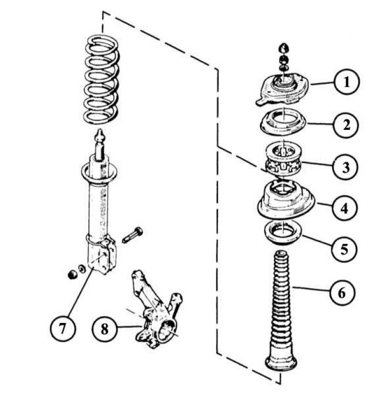
1 - tension plate; 2 - upper spring support; 3 - spring limiter; 4 - lower spring support; 5 - support on the pivot pin; 6 - dustproof cuff; 7 - shock absorber assembly; 8 - steering swivel support. To facilitate assembly, it is necessary to mark the installation locations.
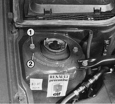
To facilitate subsequent installation, you must definitely mark in which receiving holes the shock absorber strut was fixed, otherwise you can violate the entire geometry of the wheel and steering. shock absorber mount «1» designed for vehicles with power steering, shock absorber mount «2» Designed for car racks without steering gear servo.
This requires a tensioner (tool Renault Sus.1052) or at least 2 standard coil spring tensioners. Without them, there is a risk that a heavily tightened helical spring, after loosening the central fixing bolt, will abruptly jump out of its mounting. Be careful, there is a very high chance of injury!
1. Remove the shock absorber.
2. Clamp the shock absorber in a vise (do not forget the protective cheeks) and slowly pull it off with the turnbuckle until the poppet discs are unloaded (about 10 mm). In order for the spring to be compressed evenly, the tie rods
3. Install the clamping device by screwing it alternately from different sides. When doing this, make sure that the spring sits exactly in the clamping device.
4. Remove the piston rod top ring.
5. Remove the poppet disc, stub axle support, spring support, dust collar and limiter from the shock absorber strut.
6. If the spring needs to be replaced, slowly decompress it. If only the shock absorber needs to be replaced, leave the spring compressed.
7. When assembling, make sure that the spring seats are clean.
8. Check the shock absorber. It should move evenly, heavily and without shocks during compression and tension. A small amount of leaked shock absorber fluid can be ignored.
9. When assembling the upper spring seat, make sure that the bearing sits correctly and is not skewed.
10. Install new (!) hard top ring.
11. Slowly loosen the spring.
Note. Recommendation: When replacing the spring, be sure to pay attention to the correct marking of the spring. It is applied to the coils of the spring.