
Operating principle of the exterior light switch, direction indicators and fog light and wiper switch
Lever switches for exterior lighting, direction indicators and fog lights and wipers form a single non-separable unit, called «steering column switch block».
This element consists of one control stage, made on diodes and switches.
When certain contacts of the steering column switch block are closed, the UCH recognizes the driver's input.
Example: the closure of contacts 12 and 14 is determined by the UCH as a command to turn on the right turn indicators.
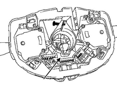
Pic. 7.93. Connection to the diode contacts of the steering column switch block
Permanent connections 4-3, 12-5, 8-2, 13-14, 10-9 are used for diagnosing the steering column switch box and UCH connection circuits.
Table 7.7. Diagnostics of the steering column switch block and connection circuits with the UCH
| Pin 4 | Contact 12 | Contact 8 | Contact 13 | Contact 10 | |
| On pin 3 | Diagnostics 1 | Switching off outdoor lighting | Intermittent wiper operation (sensitivity 1) | marker light | high beam headlights |
| Contact 5 | Switching off the wipers | Diagnostic 2 | High beam signaling | Switching headlights | Fog lights |
| Contact 2 | Rear fog light | Diagnostic 3 | Rear window cleaner | Button «control of data output to the on-board computer display» | |
| Contact 14 | Left turn indicator | Right turn indicator | Automatic dipped beam switch (only with rain sensor) | Diagnostics 4 | |
| Contact 9 | Intermittent wiper operation (sensitivity 2) | Intermittent wiper operation (sensitivity 3) | Intermittent wiper operation (sensitivity 4) | High wiper speed | Diagnostics 5 |