



Contents: Removal antennas 🠛 Removal the rear antenna 🠛 Installation 🠛 Connecting the opening antenna 🠛
Cars equipped with the "hands-free" system have presence sensors and body element opening antennas for card recognition:
- opening antenna in the outer handle of each door,
- opening antenna in the rear bumper,
- presence sensor in the outer handle of each door.
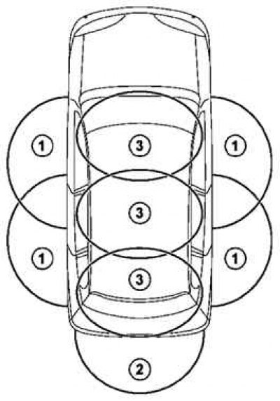
Fig. 7.44. Door opening antenna placement diagram: 1 – opening antennas located in the outer door handles; 2 – opening antenna located in the rear bumper; 3 – engine start antennas
Note: The engine start antennas have no effect on unlocking the vehicle. In contrast, it is not possible to lock the vehicle using the "lock" switches located on the outside handles if the card is in the engine start zone.
Note: Motion sensors are built into presence sensors.
Removal antennas
For hands-free operation, the outer door handles are equipped with:
- presence sensors to recognize the user's hand in combination with a reflector mounted on the handle;
- with the lock button;
- opening antenna built into the handle (Fig. 7.45).
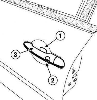
Fig. 7.45. Components of the door opening system: 1 – presence sensors; 2 – lock button; 3 – opening antenna
Note: Only vehicles equipped with the hands-free system have a lock switch.
Note: If the car has not been used for approximately 72 hours, the presence sensors are switched off. In this case, the unlocking command is detected by the handle movement sensor. The presence sensor and the handle movement sensor are assembled.
Removal the rear antenna
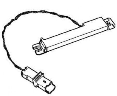
Fig. 7.46. External view of the rear antenna
Remove the rear bumper.
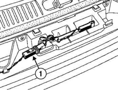
Fig. 7.47. Removing the rear antenna: 1 – connector
Disconnect the antenna connector and remove it (Fig. 7.47).
Installation
Installation is carried out in the reverse order of removal.
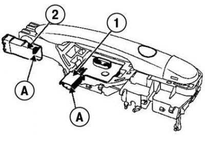
Fig. 7.48. Opening antenna connection connectors: A – connection contacts; 2 – connector 1; 3 – connector 2
Connecting the opening antenna
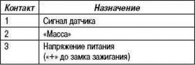
Presence and motion sensors (connector 2)
Article reprinted from the website www.RenaultBook.ru
Opening antenna and locking switch (connector 3)
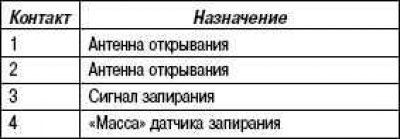
Note: The locking switch is checked with an ohmmeter by connecting it to contacts 3 and 4.
Note: The resistance value of the opening antenna is approximately 0.2 ohms.