
Removing
Note. Before working on the safety components, the airbag computer must be locked using the diagnostic tool. In this case, all ignition circuits are blocked, and the airbag warning light on the instrument panel lights up with a constant light (with the ignition on).
Note. When the airbag computer is locked, the electric steering column lock is also unlocked.
Attention! It is strictly forbidden to work with pyrotechnic systems (airbags and seat belt pretensioners) near heat sources or open flames, as there is a risk of airbags or seat belt pretensioners deploying.
Disconnect the wires from the battery terminals, starting with the negative terminal.
Remove the center console.
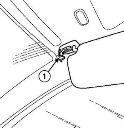
Pic. 7.58. Sun Visor Fixator: 1 - latch
Press the sun visor latch (pic. 7.58).
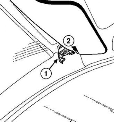
Pic. 7.59. Removing the sun visor: 1 - stopper; 2 - visor
Remove the stopper and sun visor (pic. 7.59).
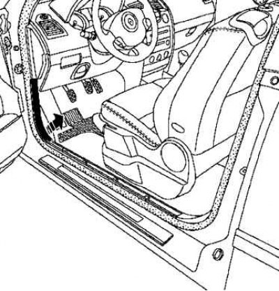
Pic. 7.60. Removal of facing of a forward threshold
Detach front sill trim (pic. 7.60).
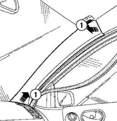
Pic. 7.61. Removing the windshield pillar trim: 1 - lining of the rack
Detach the windshield pillar trim (pic. 7.61).
Remove the tweeter grilles and the speakers themselves.
Pic. 7.62. Removing the access hatch cover to the lower casing
Detach the hatch cover to the lower casing (pic. 7.62).
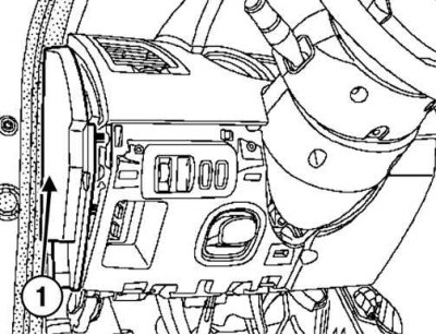
Pic. 7.63. Removing the side shield: 1 - shield
Remove the side shield (pic. 7.63).
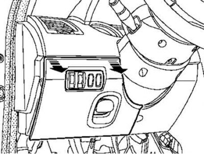
Pic. 7.64. Removing the headlight range control switch panel and instrument lighting dimmer: 1 - stopper; 2 - screws; 3 - panel of the switch of the corrector of headlights and a regulator of brightness of illumination of devices
Unscrew the screws, disconnect the stopper and remove the switch panel for the headlight range control and dimmer switch (pic. 7.64).
Attention! Stoppers must be replaced after each removal.
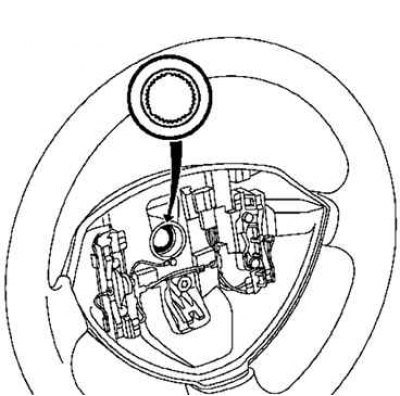
Turn the steering wheel half a turn to gain access to the hole.
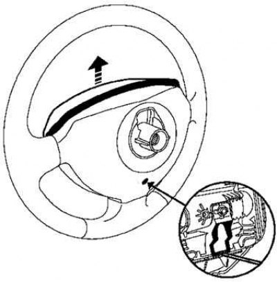
Pic. 7.65. Removing the steering wheel airbag capsule
Insert a screwdriver into the hole and remove the airbag capsule (pic. 7.65).
Pic. 7.66. Removing the airbag connector holder
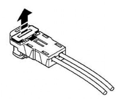
Remove the airbag connector holder with a flat blade screwdriver (pic. 7.66).
Pic. 7.67. Removing the airbag
Remove the driver's airbag from the steering wheel (pic. 7.67).
Set the wheels to straight ahead.
Pic. 7.68. Removing the steering wheel: 1 - fastening bolt
Loosen the steering wheel bolt and remove it (pic. 7.68).
Pic. 7.69. Removing the steering column covers: 1 - fastening screws
Unscrew the three lower mounting screws and remove the upper and lower steering column covers (pic. 7.69).
Mark the position of the steering column switch block.
Make sure that the label on the contact disk is opposite the pointer.
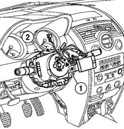
Pic. 7.70. Removing the steering column switch block: 1 - label; 2 - fastening screw
Remove the steering column switch block by unscrewing the fastening screw (pic. 7.70).
Disconnect the block from a steering column.
Disconnect the wire blocks (wiper switch, audio remote control, outdoor lighting switch, direction indicators and fog lights).
Disconnect the block of wires from the contact disk.
Pic. 7.71. Removing the second lower steering column cover: 1 - screws; 2 - top clamps
Unscrew the two screws, disconnect the two upper clips and remove the second lower stalk cover (pic. 7.71).
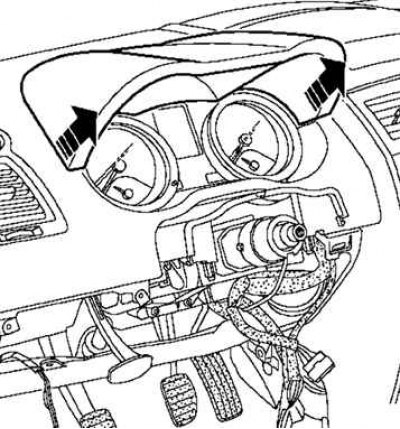
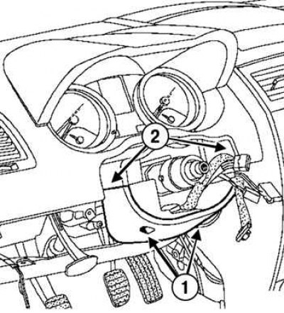
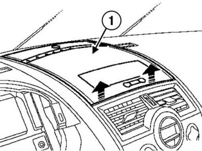
Pic. 7.72. Removing the visor of the instrument panel
Remove the instrument panel visor (pic. 7.72).
Disconnect the connector of the Carminat navigation system (depending on equipment level).
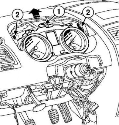
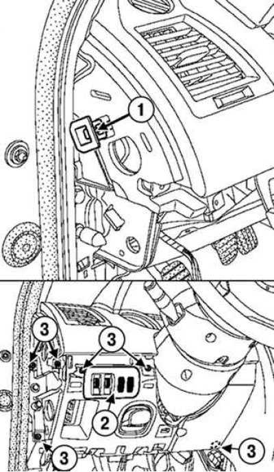
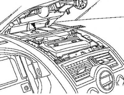
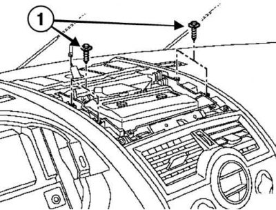
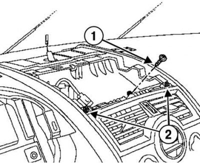
Pic. 7.73. Removing the instrument panel: 1 - screw; 2 - spring latches
Turn away the screw, wring out both spring latches and remove the instrument panel (pic. 7.73).
Pic. 7.74. Loosening the screw in the instrument cluster recess: 1 - screw
Loosen the screw in the instrument cluster (pic. 7.74).
Pic. 7.75. Detaching the top cover or display holder: 1 - top cover
Detach the top cover or display holder (the car is in the basic configuration) (pic. 7.75).
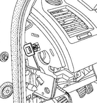
Pic. 7.76. Disconnecting the Sunlight Sensor
Disconnect the sun sensor (pic. 7.76).
Pic. 7.77. Disconnecting the Carminat navigation system: 1 - fastening bolts
Turn away bolts and remove the screen of system of navigation Carminat (if it is installed) (pic. 7.77).
Disconnect the connector.
Pic. 7.78. Top cover niche bolt and screws: 1 - bolt; 2 - screws
Unscrew the bolt and two screws in the niche of the top cover (pic. 7.78).
Pic. 7.79. Removing the Carminat Control Panel
Remove the control panel of the Carminat system (if it is installed) using a special tool (Ms. 1373) (pic. 7.79).
Disconnect the connectors.
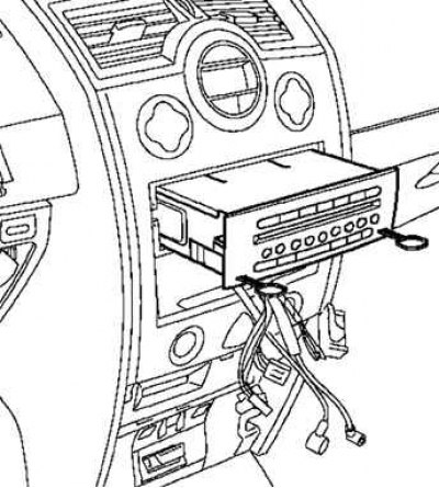
Pic. 7.80. Removing the audio system
Remove the audio system using the special tool (Ms. 1639) (pic. 7.80).
Disconnect the connectors.
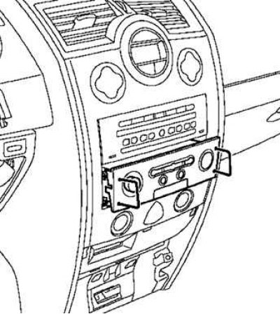
Pic. 7.81. Detaching the card reader bracket: 1 - fastening screws
Loosen the mounting screws and remove the card reader bracket using the special tool (Sag. 1597) (pic. 7.81).
Disconnect the connectors.
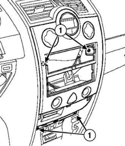
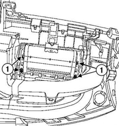
Pic. 7.82. Removing the central ventilation nozzle assembly with the climate control panel: 1 - fastening screws
Loosen the mounting screws and remove the central ventilation nozzle assembly with the climate control panel (pic. 7.82).
Note. On vehicles without automatic air conditioning, unscrew the screws, disconnect the central ventilation nozzle from the air conditioning or heating system control panel.
Remove the ventilation nozzle.
Position the air conditioner control panel so that it does not interfere with the removal of the instrument panel.
Disconnect the connectors.
Open the glove box.
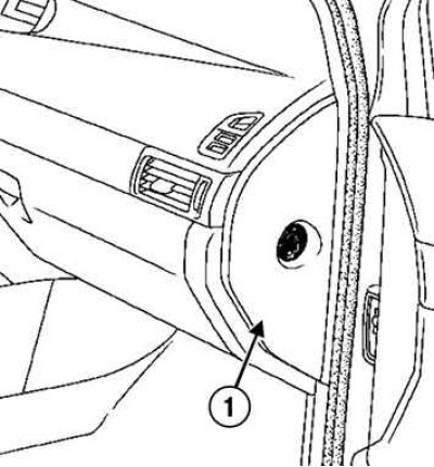
Pic. 7.83. Removing the side shield
Remove the side shield (pic. 7.83).
Turn off the front passenger's front airbag deactivation switch.
Pic. 7.84. Removing the glove box: 1 - stopper; 2 - fastening screws
Disconnect the stopper, unscrew the fastening screws and remove the glove box (pic. 7.84).
Attention! Stoppers must be replaced after each removal.
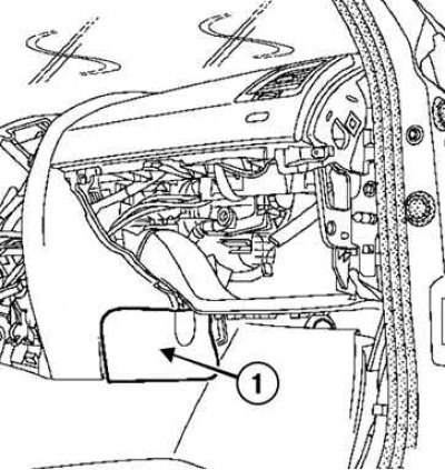
Pic. 7.85. Removing the bottom covers: 1 - covers
Detach the two bottom covers (pic. 7.85).
Disconnect the glove box light.
Disconnect the wires from the glove box light.
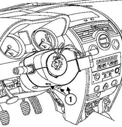
Pic. 7.86. Disconnecting power from the glove box lamp and passenger airbag: 1 – glove box lamp; 2 - fastening screw; 3 - block of wires; 4 - «mass» the wire
Loosen the mounting screw, disconnect the wiring harness from the passenger airbag and disconnect «mass» airbag wire (pic. 7.86).
Attention! Protect the wiring harness from damage before removing the instrument panel. Please note: when removing the dashboard, in its lower part, the gear lever interferes with the removal.
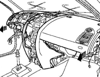
Pic. 7.87. Removing the dashboard
Remove the dashboard (this operation is performed by two people with an assistant) (pic. 7.87).
Pic. 7.88. Removing the passenger airbag module: 1 - fastening nuts
Loosen the mounting nuts and remove the airbag module (pic. 7.88).
Installation
Attention! Be sure to replace the nuts holding the passenger airbag to the dashboard every time you remove the passenger airbag.
Torque tighten the airbag module mounting screws to 2 Nm.
Pic. 7.89. Stopper installation
Install two stoppers (pic. 7.89).
Attention! Both stoppers must be replaced.
Before proceeding with installation, make sure that the wheels are still in the straight ahead position, and the steering column switch box is opposite the mark.
Pic. 7.90. Steering wheel installation
The steering wheel must slide freely into the splines (splines have orienting sections) (pic. 7.90).
Be careful not to damage the splines of the orienting sections.
Be sure to replace the mounting bolt each time the steering wheel is removed.
Tighten the steering wheel mounting bolt to the required torque of 440 Nm.
Attention! Check the airbag computer with a scan tool.
Attention! Check the cleanliness of the wiring when installing the airbag module.
Pic. 7.91. Checking the connection and blocking of the airbag connectors: 1 - connection connectors; 2 - holder fastening screw
Check the connection and locking of the airbag connectors (pic. 7.91).
Connect «mass» passenger airbag module wire.
Tighten the holder fastening screw to the required torque of 20 Nm.
Attention! Unlock the airbag computer using the scan tool.
Attach the wires to the battery terminals, starting with the positive terminal; do the necessary programming.
Torque tighten the battery cover bolts to 4 Nm.
Install the remaining components in the reverse order of removal.