type 1 (Clio) | 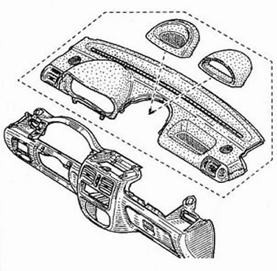
type 2 (Symbol) |
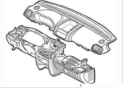
The dashboard consists of two elements - the upper and lower parts.
Removal: Type 1 (Clio)
- disconnect the cable from the negative battery terminal and wait at least 5 minutes for the airbag system to deactivate;
- remove the center console (see above);
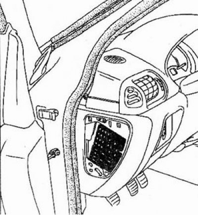
- partially remove the door seal;
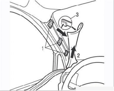
Figure 9.96. Removing the windshield pillar trim: 1 - clamps; 2 – a groove on the panel of devices; 3 - lining latch
- slightly move the upper part of the windshield pillar lining to press the latch 3 (Figure 9.96);
- disconnect facing from clamps 1;
- remove the lining from groove 2 on the front panel;
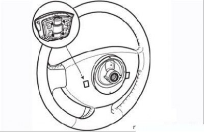
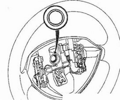
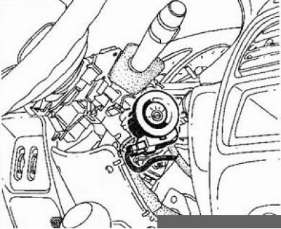
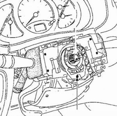
Figure 9.97. Removing the airbag module from the steering wheel
- Using a flat head screwdriver, remove the airbag module from the steering wheel by depressing the spring clips on the back of the hub (Figure 9.97);
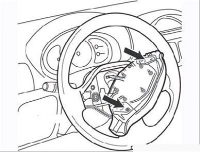
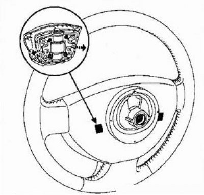
Figure 9.98. Connectors on the airbag module (arrows)
- unplug the two connectors on the airbag module (Figure 9.98);
- set the front wheels to the straight ahead position;
- unscrew the steering wheel mounting bolt and remove it;
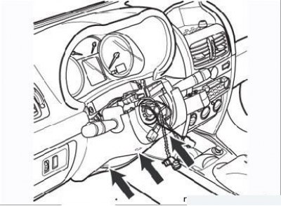
Figure 9.99. Screws of fastening of a casing of a steering column
- unscrew the three screws securing the lower part of the steering column cover (Figure 9.99);
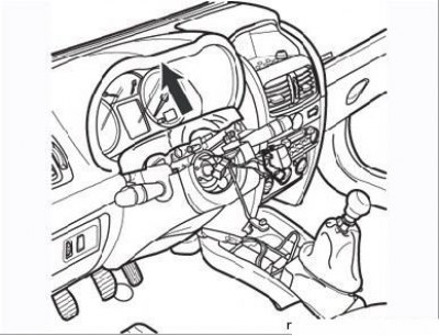
Figure 9.100. Removal of the top part of a casing of a steering column
- remove the top part of a casing of a steering column, as it is shown in Figure 9.100;
- remove the immobilizer ring antenna and the steering column switch block as described in section «Steering»;
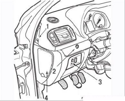
Figure 9.101. Dashboard Upper Mounts: 1 - holder (left-hand side); 2 - screw; 3 – regulator of the corrector of light of headlights; 4 - fuse block cover
- remove two holders 1 (right and left) (Figure 9.101) front panel;
- by removing the cover using the Car tool. 1597, unscrew screw 2;
- using the Car tool. 1597 Disconnect the cover of the regulator 3 of the headlight range control and disconnect the connectors;
- remove the fuse block cover;
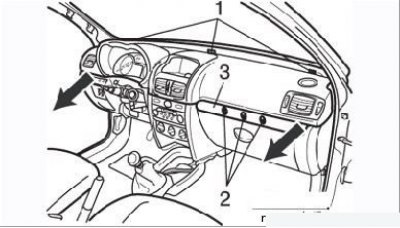
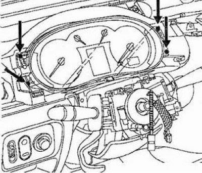
Figure 9.102. Screws 1 at the top of the instrument panel; screws 2 (located under cover 3); arrows - panel removal direction
- unscrew the three upper screws securing the upper part of the instrument panel (Figure 9.102);
- by removing the cover 3 using the tool Car. 1597, remove three screws 2;
- pull the top of the front panel in the direction of the arrows;
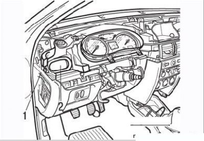
Figure 9.103. Retainer (1) dashboard (left-hand side): 2 - air duct
- remove the two clips on the right and left of the instrument panel (Figure 9.103);
- pull the air ducts towards you;
- remove the instrument cluster as indicated below;
- disconnect the two tweeter connectors (twitters);
- remove the glove box light;
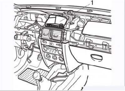
Figure 9.104. Nest (1) for the keyboard of Carminat navigation equipment or container for small items (depending on configuration)
- using the Car tool. 1597 release the spring clips and remove the keyboard of the Carminat navigation equipment (Figure 9.104) or compartment for small items (depending on configuration), disconnect the connectors;
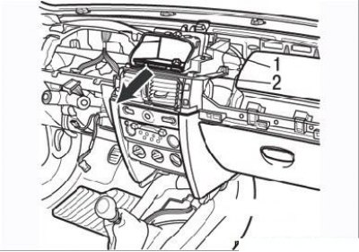
Figure 9.105. Removing the navigation display: 1 - fastening screws; 2 - clamps
- remove two screws (Figure 9.105);
- press the two latches and remove the display or monitor of the Carminat navigation system, disconnect the connector;
- remove the car radio (see section «electrical equipment»);
- disconnect the holder of the switches for controlling the heating and ventilation system and disconnect the contact connectors;
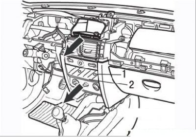
Figure 9.106. Lid (1) and two screws (2) fixing the control panel for the heating and ventilation system
- detach the cover and unscrew the two screws securing the heating and ventilation control panel (Figure 9.106);
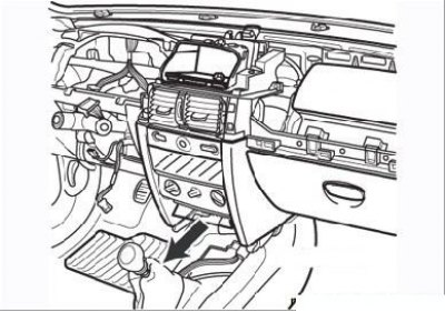
Figure 9.107. Removing the loudspeaker mounting bracket for the Carminat navigation system
- Remove the Carminat navigation loudspeaker mounting bracket (if it is installed) and disconnect the speaker connector (Figure 9.107);
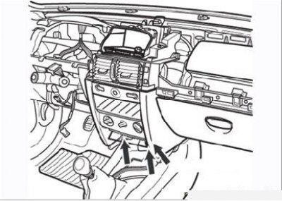
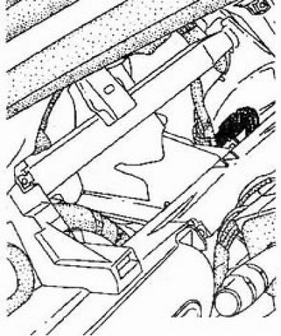
Figure 9.108. Screws of fastening of the bottom part of the panel of devices
- unscrew the three screws securing the lower part of the instrument panel (Figure 9.108);
- remove the front passenger airbag by disconnecting the two airbag connectors;
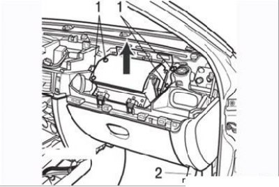
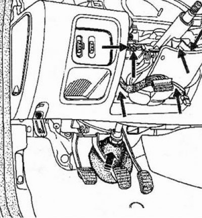
Figure 9.109. bolts (1) front passenger airbag module mounting and bottom screw (2) fastenings of the right side of the instrument panel
- turn out four bolts of fastening, then disconnect an airbag, as shown in Figure 9.109;
- unscrew the two lower screws securing the front panel (right and left);
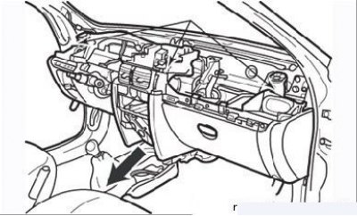
Figure 9.110. Screws of fastening of the bottom part of the panel of devices
- unscrew the three upper screws securing the instrument panel (Figure 9.110);
- lift the instrument panel slightly to remove it from the retaining tabs in the area of the mounting screws. Check again if everything is disconnected (wiring, cables and hoses) and set aside from the panel;
- together with an assistant, carefully lift and remove the right side of the panel first, remove the panel from the passenger compartment through any front door;
- if there is difficulty in removing the panel, do not use force - check again that everything is disconnected and that the panel has not caught on the body elements surrounding it.
Installation
Installation is carried out in the reverse order of removal, taking into account the following:
- after attaching the front panel to the motor shield, make sure that not a single wire, cable or hose is pinched;
- there must be no foreign objects in the airbag mounting area (screws, latches, etc.);
- on the side of the airbags, fully connect the connectors and install the airbag retainers;
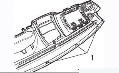
Figure 9.111. Fasteners (1) bottom of instrument panel
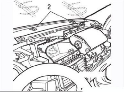
Figure 9.112. Fasteners (2) top of instrument panel
- when installing the upper part of the instrument panel, check the condition of the clips (Figure 9.111 and 9.112). If the clips 1 show signs of damage, the upper part of the panel must be replaced. Clips 2 are supplied as spare parts and can be replaced;
- when installing the steering column switch block, make sure that the front wheels are in the straight-ahead position;
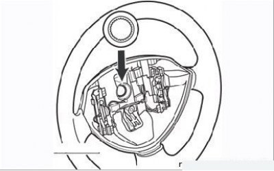
Figure 9.113. Steering wheel spline configuration
- when installing the steering wheel, please note that the splines of the steering wheel hub have a special configuration (Figure 9.113), to protect against incorrect connection. The steering wheel must fit freely on the splines of the steering column. After each removal, be sure to replace the steering wheel bolt and tighten to the specified torque;
- after the final installation of the instrument panel, check the functioning of all elements installed on it.
Panel removal: Type 2
Before removing the front panel, the steering column must be dismantled, see "Steering".
Attention! Airbag models.
- Do not place airbag units (driver or passenger) near a source of heat or an open flame: the risk of spontaneous explosion of the device.
- only qualified personnel with sufficient skills to carry out the work is allowed to work with the passive safety system.
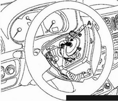
- Always disconnect the connector before removing the steering wheel (A) airbag unit to prevent spontaneous detonation of the device.
1. Disconnect the battery.
2. Models with an airbag: use a screwdriver to unfasten the clips securing the airbag unit.
3. Models without airbag: remove the steering wheel pad (fastening with clips).
4. Turn away and throw out a bolt of fastening of a steering wheel.
5. Set the steered wheels to the straight ahead position and remove the steering wheel.
6. Turn away three bolts of fastening of casings of a steering column, remove casings.
7. Disconnect the connectors of the wiper/washer switch and airbag unit current collector (if installed). On models with airbag
8. Mark the relative position on the halves of the current collector body. Make sure the steer wheels are in the straight ahead position, the slip collector connector is in the center of the steering wheel, and the mark "ABOUT" on the current collector is located opposite the benchmark "E".
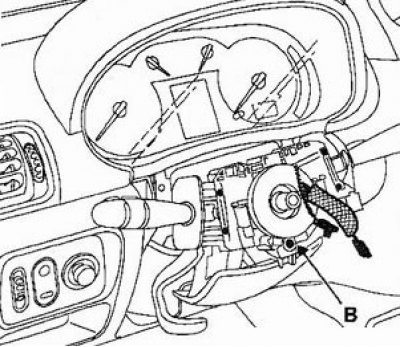
9. Remove the bolt (IN). Use a flat screwdriver to press the cone lock and remove the current collector.
10. Remove a cover of the lever of a gear change.
11. Remove the ashtray.
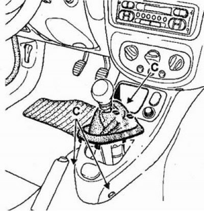
12. Turn away bolts (WITH) front console, remove the front console.
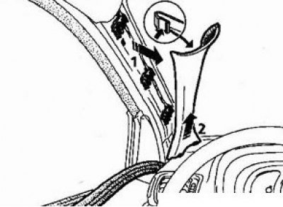
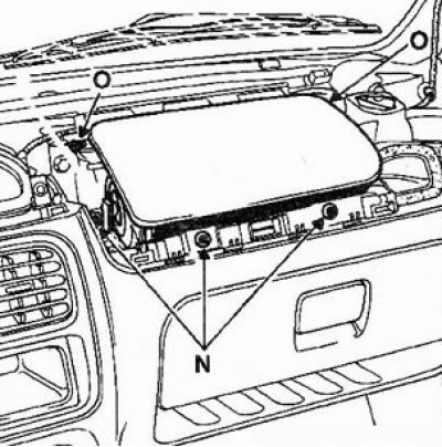
13. In the direction of the arrows (1) And (2) remove the front struts "A".
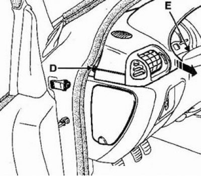
14. Remove the two side bolts (D) and two central bolts (E) fastening the front panel.
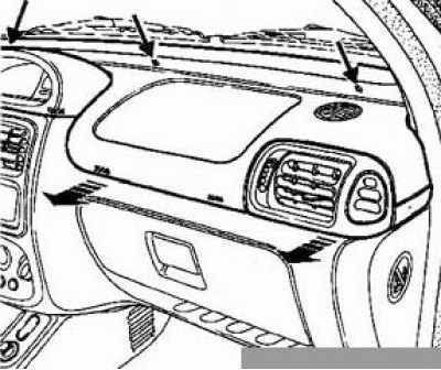
15. Turn away three top bolts of fastening of an overlay of the forward panel and remove the panel in the direction of arrows.
16. Remove the immobilizer antenna (the antenna is located at the ignition switch).
17. Turn away four bolts of fastening of the block of devices, disconnect sockets and remove the block of devices.
18. Disconnect the ignition lock connector.
19. In the engine compartment:
- Remove the intake duct.
- Turn away bolts of fastening of a broad tank, remove a tank from a support and fix it aside.
20. Turn away a bolt of fastening of the cardan hinge of a steering shaft to the steering mechanism.
21. Turn away six bolts of fastening of a steering column. Pull out the engine compartment bulkhead boot.
22. Remove the steering column.
23. Remove the cover of the fuse box in the passenger compartment.
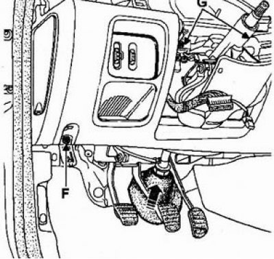
24. Remove the bolts (F) And (G) front panel mounting.
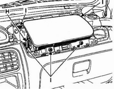
25. Models with airbag: disconnect the connector (H) and unscrew the bolts (I) passenger airbag mounts.
26. Remove two bolts (J) securing the heater control panel, remove the control panel from the front panel.
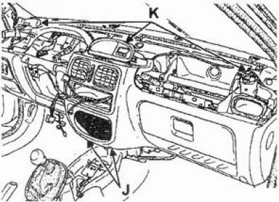
27. Remove three bolts (TO) front panel fasteners.
28. Remove the radio.
29. Disconnect the center display connector (if installed).
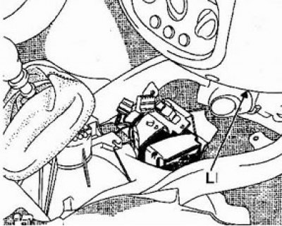
30. Remove the bolt (L) front panel mounting.
31. Raise the front panel until the guide pins located next to the bolts are released (TO).
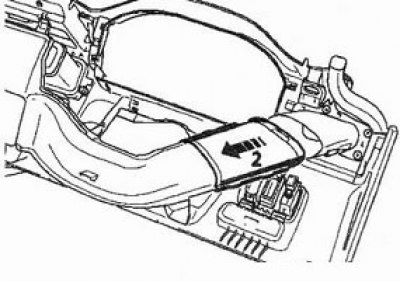
32. Pull the front panel in the direction of the arrow (1).
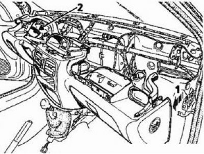
33. Arrow (2) slide the air duct from the left side of the panel.
34. Remove the front panel with two people.
Installation
Installation is carried out in the reverse order.
Note. Installation of the steering column is described in the section "Steering".
Installation Notes
Combination switch
Make sure the wheels are in the straight ahead position.
Check that the contact disk is installed in the middle (2.5 turns each way).
Install the assembled assembly on the steering column and connect all the connectors.
Complete the installation and tighten the bolt "M" only after both halves of the trim casing have been installed, while the lever switches must be installed without distortion relative to the instrument panel and dashboard.
This operation is facilitated by a cutout in the lower casing, which gives access to the bolt "M".
After each removal, replace the steering wheel bolt with a new one (the new bolt has a microcapsule with glue).
Tightening torques
- Bolt connecting the fork of the universal joint of the steering shaft - 25 N·m
- Steering wheel mounting bolt - 45 Nm
- Steering column nuts - 20 Nm
- Airbag mounting bolt - 5 Nm
Passenger airbag
Check for foreign objects in the space for the pillow block.
Connect the airbag side connector securely. Tighten the bopts (N) fixing the block with a torque of 6 Nm.
Steering wheel
The steering wheel splines are made like this. which ensures an unambiguous landing of the steering wheel.
When installing, check the freedom of installation of the wheel on the spitz. Do not reinstall the steering wheel bolt.