



Contents: Removal the casing (decorative…🠛 Removal the steering column 🠛 Installing the steering column 🠛 Special installation instructions 🠛
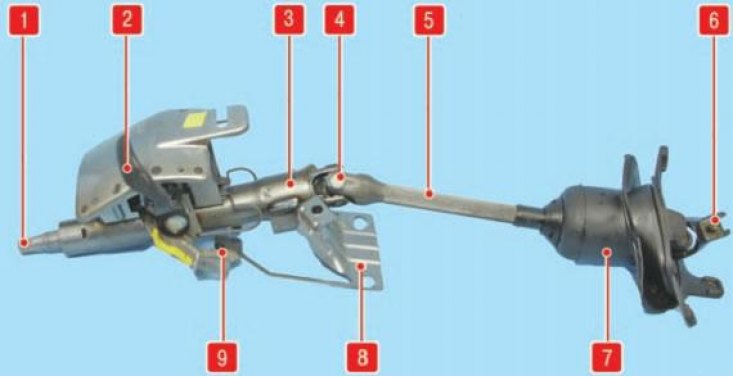
Steering column: 1 - steering shaft; 2 - steering column adjustment lever; 3 - steering column; 4 - upper cardan joint of the intermediate shaft; 5 - intermediate shaft; 6 - lower cardan joint of the intermediate shaft; 7 - intermediate shaft seal; 8 - steering column mounting bracket; 9 - steering column adjustment mechanism
Caution! Models with airbag. Do not place airbag units (driver or passenger) near a heat source or open flame: risk of spontaneous detonation of the device.
Tightening torques:
- Steering shaft universal joint bolt - 25 Nm
- Steering wheel bolt - 45 Nm
- Steering column support nuts - 20 Nm
- Airbag unit bolts - 5 Nm
Some cars have a steering column with two cardan joints. Removing such a steering column has some peculiarities.
Removal the casing (decorative panel) steering column
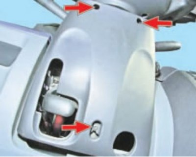
Remove the three screws securing the steering column cover.
 |
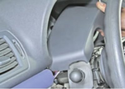 |
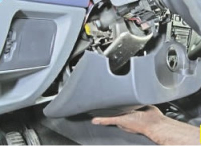
Remove the lower and upper parts of the casing
Removal the steering column
1. Disconnect the battery.
Models without airbag
2. Release the steering wheel cover from the clips.
Models with airbag
3. Remove the two airbag module mounting bolts (below the steering wheel) and disconnect the module connector (D). The connector has a built-in device to prevent spontaneous detonation: always disconnect the connector when removing the airbag module.

4. Loosen the steering wheel mounting bolt.
5. Set the steering wheels to the straight-ahead position and remove the steering wheel.
6. Unscrew the steering column cover mounting bolts (three pieces) and remove the covers.
7. Disconnect the wiper/washer switch connector and the airbag current collector.
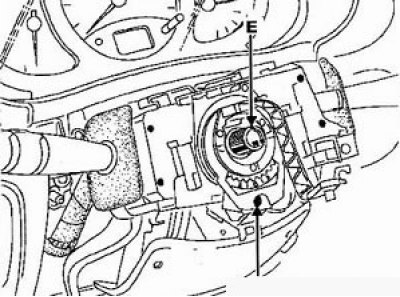
8. Apply relative position marks to the halves of the current collector housing. Make sure that the wheels are in the straight-ahead position, the current collector connector is in the center of the steering wheel, and the "O" mark on the current collector is opposite the "E" reference mark.
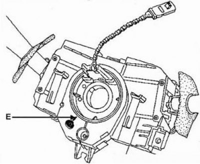
Current collector from Valeo.
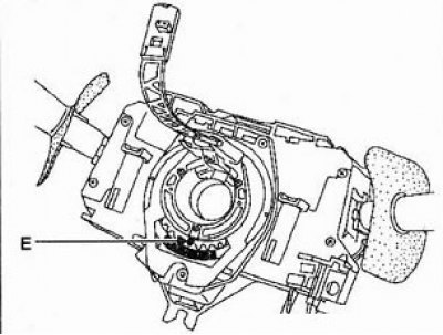
Current collector from Lucas.
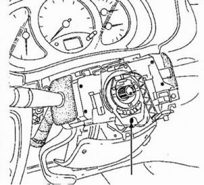
9. Loosen the bolt (C). Using a flat-head screwdriver, press the cone lock and remove the current collector.
10. Remove the side windshield pillar trims: press the clip (1) and pull the trim (2) out of the lower support.
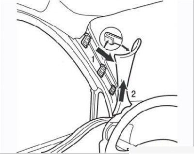
Figure 6.10. Removing the windshield pillar trim: 1 – clip; 2 – overlay
11. Unscrew the two side screws securing the upper trim of the front panel.
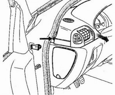
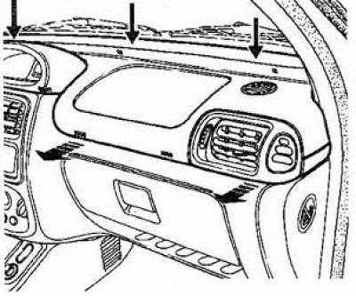
12. Loosen the three upper screws securing the upper front panel trim. Remove the upper trim in the direction of the arrows shown in the figures.
13. Remove the immobilizer signal receiver.
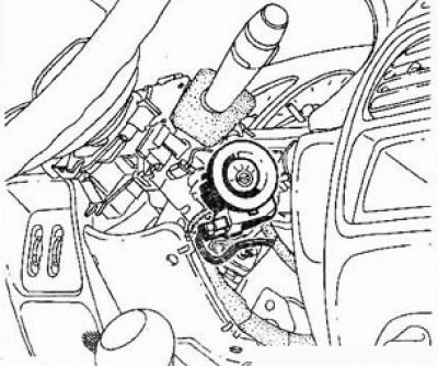
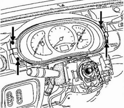
14. Unscrew the six instrument cluster mounting bolts, disconnect the four connectors and remove the instrument cluster.
 |
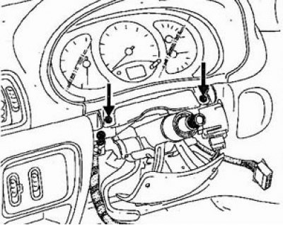 |
15. Disconnect the steering column connector.
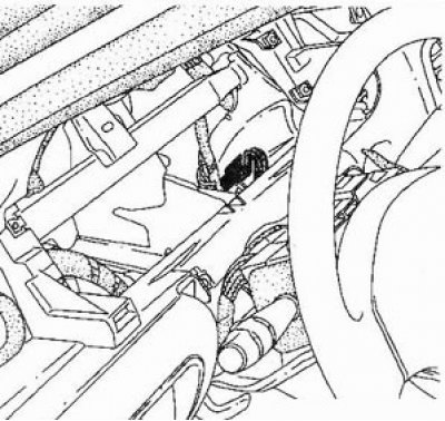
16. In the engine compartment:
- Disconnect the air intake duct.
- Loosen the expansion tank mounting nuts and remove the tank to gain access to the steering shaft joint.
17. Unscrew and remove the eccentric bolt of the terminal connection of the universal joint fork of the steering folding telescopic shaft, marking the relative position of the splined parts;
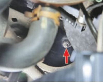 |
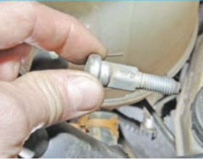 |
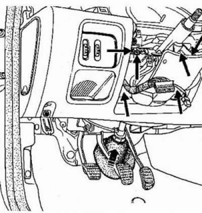
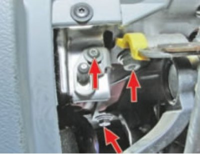
18. Unscrew two bolts and one screw securing the cover from the steering column, pull the cover out of the engine compartment bulkhead.
 |
 |
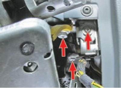
19. Remove the steering column.
Installing the steering column
1. Install the steering column.
2. Install the column cover into the engine compartment bulkhead. Tie the cover legs and the cardan joint with a plastic clamp, as shown in the figure.
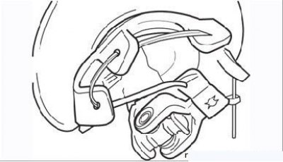
Figure 6.17. Pass the plastic clamp through the holes in the protective cover (or a whip), to install the cover on the engine shield
- tie the protective boot flaps and the steering shaft cardan joint fork with twine (see Figure 6.17), push it into the hole in the engine shield;
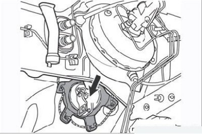
Figure 6.21. Installing the protective cover for the folding steering shaft in the engine compartment
- cut the string that connects the boot flaps to the cardan joint fork and install the boot on the front engine shield (Figure 6.21);
- install the eccentric bolt of the universal joint yoke terminal connection without tightening it;
- pull up and place the splined portion of the folding shaft onto the steering column;
- by turning the steering wheel, achieve free access to the bolt of the upper fastening of the folding shaft, then screw in the bolt;
- tighten the upper mounting bolt of the folding shaft to the specified torque, after lubricating its threaded part with a compound that prevents spontaneous loosening;
- align the steering column with the vehicle wheels and the mark on the steering wheel;
- tighten the eccentric bolt of the universal joint yoke terminal connection to the specified torque;
- install the air duct, central electronic switching unit, headlight corrector knob holder, fuse box cover, front pillar trim, left door seal, hood lock actuator handle;
- check and, if necessary, adjust the front wheel alignment.
Special installation instructions
- a) The steered wheels must be in the straight-ahead position.
- b) When installing the airbag module current collector, the "O" mark must be aligned with the "E" reference mark.
- c) Do not tighten bolt (C) until the steering column covers are installed. To tighten bolt (C), cut an access hole in the lower cover.
- d) Do not reinstall the steering wheel mounting bolt. The tightening torque of the bolt is 45 Nm.
Caution: Before connecting the airbag module, perform a passive restraint system check:
- Turn on the ignition and make sure that the passive restraint system indicator is on.
- Connect the airbag connector: the indicator should go out.
- Turn off the ignition, install the airbag module in place. Tighten the mounting bolts to 5 Nm.
- Turn on the ignition: the indicator should light up and go out after about three seconds.
If there are deviations from the indicator operation description, troubleshoot the passive safety system, see the relevant section. Neglecting to check the system may result in an accident.