



Contents: Disassembly 🠛 Assembly 🠛
Disassembly
- disconnect the negative battery cable;
- remove the steering wheel as described above;
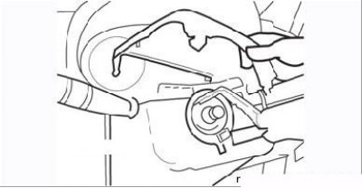
Figure 6.6. Removing the decorative upper panel of the steering column
- unscrew the three mounting screws under the steering column and first remove the decorative upper steering column trim (Figure 6.6), and then, moving it down and releasing it from the latches, the lower cover;
- disconnect the wire connectors from the steering column switches (windshield wipers and exterior lighting) and disconnect the contact disk connector. Mark all disconnected connections;
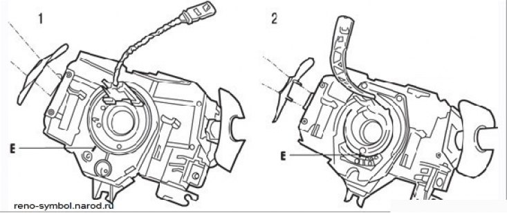
Figure 6.7. Position the fixed mark "E" on the steering column switch opposite the mark "O" on the contact ring: 1 – steering column switch in VALEO version; 2 – steering column switch in LUCAS version
- before removing the steering column switch assembly, it is essential to mark the position of the contact disc. To do this, make sure that the wheels are in the straight-ahead position to center the conductive tape and that the "O" mark on the contact ring is opposite the fixed "E" mark (Figure 6.7);
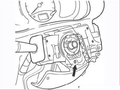
Figure 6.8. Steering column switch mounting clamp screw
- unscrew the clamp mounting bolt (Figure 6.8), then apply a sharp blow with the screwdriver to release the cone and remove the steering column switch;
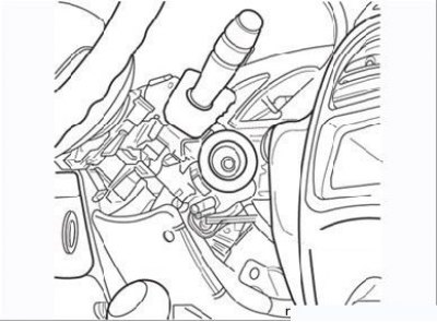
Figure 6.9. Electronic anti-theft engine start interlock receiver ring
- remove the electronic anti-theft engine immobilizer system receiver ring (Figure 6.9);
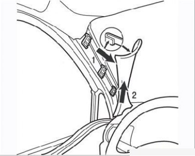
Figure 6.10. Removing the windshield pillar trim: 1 – cladding; 2 – overlay
- remove the upper part of the instrument panel by pulling back the windshield pillar trim. To do this, simply detach the trim enough to be able to press the upper latch, then pull back the trim 1 (Figure 6.10) and detach it from the overlay 2;
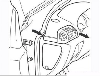
Figure 6.11. Side screw for fastening the instrument panel (left side of the panel)
- remove the two side screws securing the instrument panel (Figure 6.11);
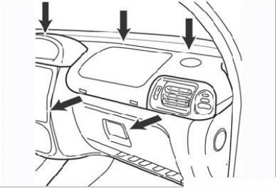
Figure 6.12. Four screws securing the instrument panel
- remove the three screws on top (near the windshield) (Figure 6.12) and completely remove the top part of the instrument panel;
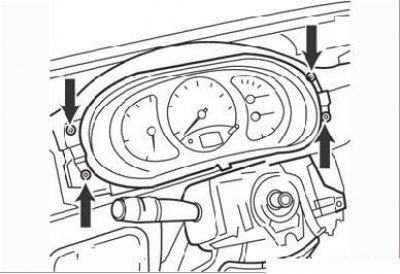
Figure 6.13. Four screws securing the instrument cluster
- remove the six instrument cluster mounting screws (Figure 6.13 and 6.14), disconnect the four connectors and remove the instrument cluster;
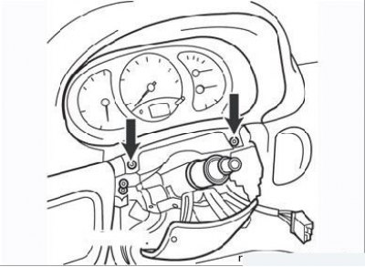
Figure 6.14. Two screws securing the instrument cluster
- release the latch and disconnect the ignition switch (lock) wiring connector;
- in the engine compartment, remove the air duct, unscrew the expansion tank mounting nuts and remove the tank to gain access to the steering shaft cardan joint fork;
- unscrew the bolt securing the steering shaft cardan joint fork, before disconnecting the shaft, mark the relative position of the splined parts;
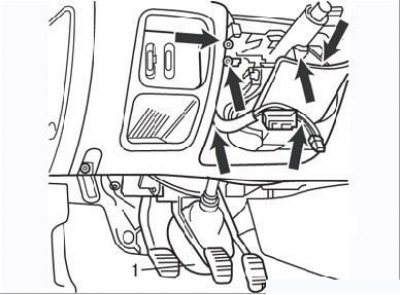
Figure 6.15. Six steering column mounting bolts (arrows) and protective cover (1) of the engine shield
Material is located on the source website (RENAULTBOOK)
- remove the six steering column mounting bolts (Figure 6.15) and pull the protective cover of the engine shield;
- remove the steering column;
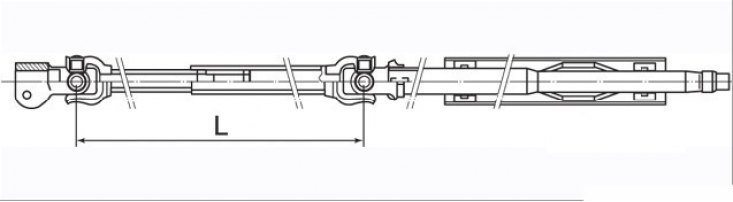
Figure 6.16. Control dimension of the intermediate shaft of the steering column: L=(416.6±1.5) mm
- inspect the removed steering column. The intermediate shaft of the column is equipped with a telescopic safety element, which in the event of a vehicle impact is compressed, preventing injury to the driver's chest. The length of the telescopic part of the shaft should be (416.6±1.5) mm (Figure 6.16). If the shaft length differs from the specified one, the steering column assembly is replaced. Check the play in the cardan joints of the steering column, the turns of the cardan joint forks should be easy, without jamming. In case of damage, replace the steering column completely.
Assembly
- from the car interior, install the steering column, aligning the splined connection of the shaft and steering gear according to the previously made marks;
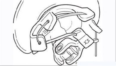
Figure 6.17. Thread a string through the holes in the protective cover to install the cover on the engine shield
- tie twine around the steering column boot and the universal joint fork (Figure 6.17) and pull it from under the car into the hole in the engine shield. Once the cover is in place, cut the string;
- install the eccentric bolt with the nut, tighten the connection to the specified torque. Install the protective cover of the connection in place.
Perform the remaining operations in the reverse order of removal, paying attention to the following:
- make sure the front wheels are in the straight ahead position;
- install the steering column switch correctly, aligning the fixed mark with the moving mark (see Figure 6.7);
- connect all the contact connectors according to the previously made marks;
- complete the installation and tighten the screw of the steering column paddle mounting clamp only after both halves of the steering column paddle housing have been installed, while the steering column paddle levers must be installed without tilting relative to the instrument cluster. This operation is facilitated by a cutout in the lower steering column paddle housing, providing access to the said screw;
- after each removal, replace the steering wheel mounting bolt with a new one (it is equipped with a microcapsule with glue).