



The system includes two pyrotechnic devices mounted on the sides of the front seats and an electronic control unit.
The ECU is mounted under the center console and consists of a deceleration sensor and an amplifier unit. If the sensor detects deceleration above a certain limit, the amplifier unit sends a signal to the fuses in the blocks
seat belt tensioners. On most models, the electronic control unit for the pretensioners is integrated into the airbag control unit.
Once the fuse is triggered, a small cap instantly releases gas, filling the pretensioner cylinder. The piston in the cylinder, moving along the cylinder, pulls the cable (about 70 mm), tightening the seat belt accordingly.
After the seat belt pretensioner has been triggered, it is replaced.
Do not expose the pretensioners to excessive heat. If any work on the vehicle requires strong impacts on vehicle parts, remove the pretensioner control system fuse by disconnecting the power supply and wait at least 5 minutes for the system to deactivate. When installing any systems with magnets (for example, loudspeakers), do not place them close to the pretensioner control unit.
Disconnection procedure (deactivation):
- turn off the ignition;
- remove the system fuse (see section "Electrical equipment");
- wait at least 5 minutes before starting work;
- working under each seat in turn, disconnect the system wiring connector.
Connection (activation) procedure:
- connect the system's contact connectors under the seats;
- install a system fuse.
Removal and installation the pretensioner unit
Removal
- deactivate the system (see above);
- remove the front seat;
- remove the front seat trim;
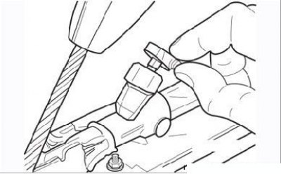
Figure 9.120. Disconnecting the connector from the pretensioner unit
Original article is on the portal Renaultbook.ru
- disconnect the wiring connector at the top of the pretensioner assembly (Figure 9.120) and pass the wiring through the trim (leave the wiring attached under the seat);
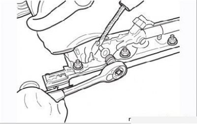
Figure 9.121. Removing the bolt securing the pretensioner unit from the seat frame
- remove the pretensioner assembly mounting bolt (Figure 9.121), remove the assembly from the seat frame.
Installation
- feed the pretensioner wiring through the slot in the seat trim and connect the connector to the unit;
- install the block into the seat, screw in and tighten the mounting bolt;
- install the seat cover;
- install the seat;
- activate the system as described above.
Removal and installation the ECU
Removal
- deactivate the pretensioning system;
- remove the center console;
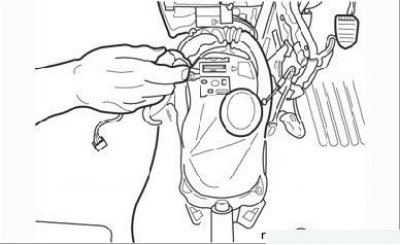
Figure 9.122. Unscrewing the screws securing the air ducts to the ECU bracket
- unscrew the mounting screws and move the two air ducts to the side (Figure 9.122);
- remove the mat to gain access to the ECU. The mat can be cut to make the work easier;
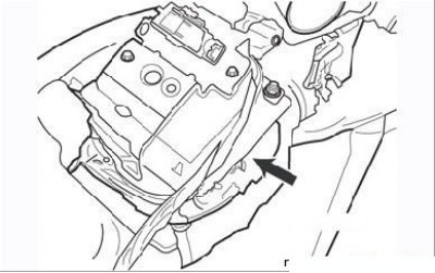
Figure 9.123. Releasing the wiring retainer and disconnecting the ECU connectors
- disconnect the ECU connectors (Figure 9.123);
- unscrew the ECU mounting nuts;
- lift the ECU and remove it from the floor together with the diagnostic connector bracket.
Installation
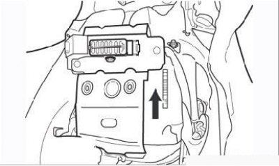
Figure 9.124. The arrow on the ECU housing is directed in the direction of the vehicle
- install the ECU in place so that the arrow on its body points in the direction of the vehicle's movement (Figure 9.124);
- install the ECU mounting nuts and tighten them securely. Do not connect the connectors until the nuts are tightened;
- connect the ECU connectors;
- install the air ducts by screwing in the screws that secure them;
- put the center console back in place;
- activate the pretensioning system.