



Contents: Removal 🠛 Installation 🠛 Features of the contact disk 🠛 Features of the instrument panel…🠛 Steering wheel features 🠛
Attention! Only experienced workers who have undergone special training are allowed to work on airbag and seat belt pretensioner systems.
Attention! It is prohibited to carry out any work with pyrotechnic systems (airbags and seat belt pretensioners) near a heat source or open flame, as there is a risk of them being triggered.
Note: When the airbag ECU is locked, the electric steering column lock is unlocked.
Removal
Place the front seats against the dashboard to remove the center console mounting screws.
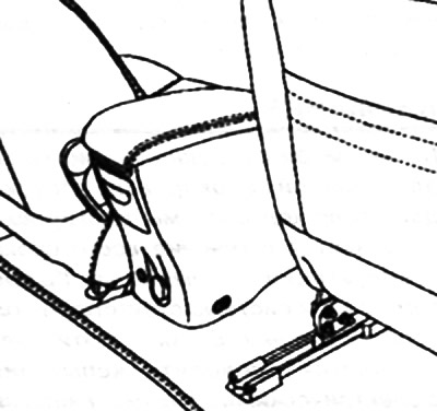
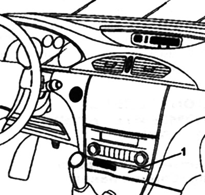
Place the seats in the rearmost position and remove the Renault 1 card reader.
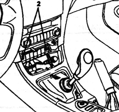
Remove the screws securing the console to the dashboard 2.
Remove:
- center console;
- car radio (8 depending on the configuration);
- central electronic communication unit (depending on the configuration);
- ECU for heating and ventilation system.
Features on cars with cable-operated dampers
Remove:
- decorative control panel trim;
- mounting screws;
- control Panel;
- instrument panel mounting bolt 1.
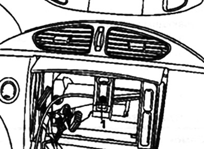
Remove the remote display of the car radio or the monitor of the Carminat navigation system (depending on the configuration), then release the wire harness.
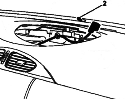
Remove:
- solar radiation intensity sensor 2;
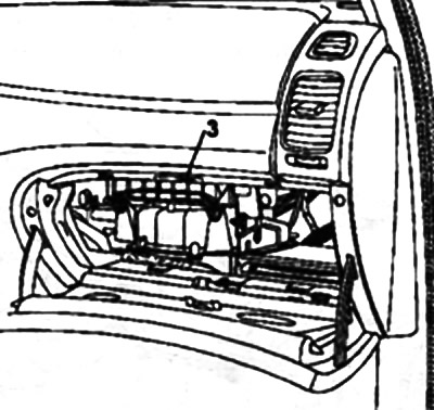
- inner lid of the glove compartment;
- secured with one screw;
- glove compartment light, paying attention to rod contact 3;
- lamp for illuminating the space under the dashboard.
Loosen the airbag mounting clamp to the beam using a 13 mm wrench or remove the mounting bolt (depending on the configuration).
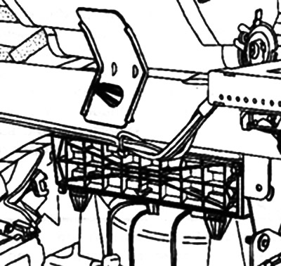
Note: Replace the holder each time it is removed.
Disconnect the passenger airbag connector located near the additional fuse/relay box.
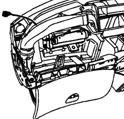
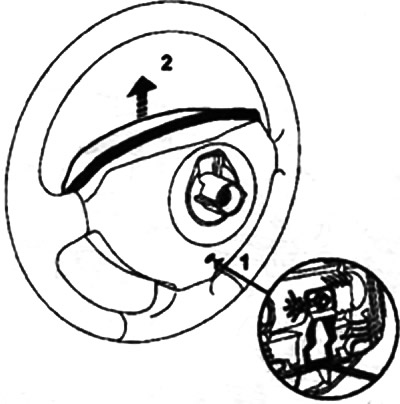
Disconnect the steering wheel airbag. To do this, insert a screwdriver into the hole 1 and pull the airbag out with an upward movement 2.
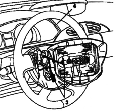
Disconnect the steering wheel airbag connectors 3 and the cruise control button connectors (depending on the configuration).
Remove:
- steering wheel mounting bolt;
- steering wheel after setting the wheels to the straight-ahead position;
- instrument panel visor 4;
- steering column trim covers;
- switches.
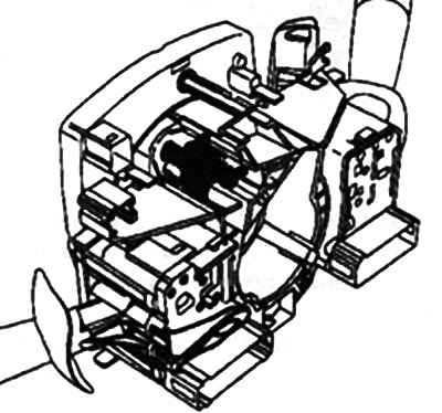
Disconnect the switch connectors (windshield wipers, car radio control and external lighting switch, turn signals and fog lights), contact disk connectors (airbags and cruise control) and steering wheel angle sensor.
Before removing the contact disk assembly, mark its position:
- after making sure that the wheels are set in the straight-ahead position;
- making sure that the "O" mark on the contact disk is located opposite the pointer.
Remove the bolt and remove the steering column assembly.
Remove the instrument panel.
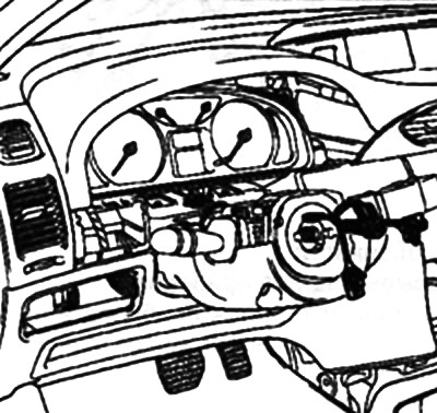
Loosen the instrument panel mounting screw 1.
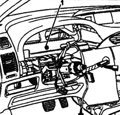
Remove:
- side panels of the instrument panel;
- side screws for fastening A of the instrument panel.
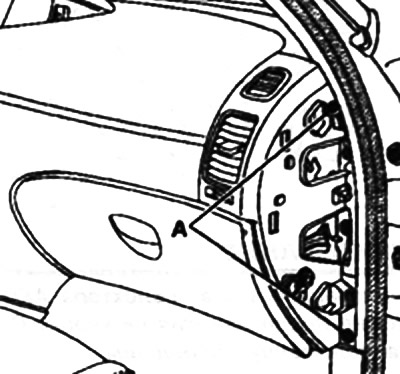
Remove the high-frequency speakers and sun visors.
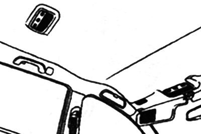
Remove the windshield pillar trim; to do this, simply pull back part of the trim to press the top latch, then move and remove the trim.
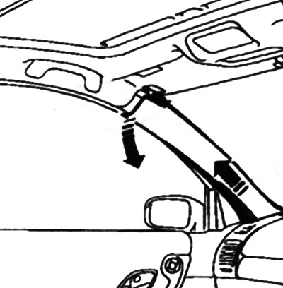
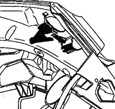
Press the spring clips and remove the instrument panel.
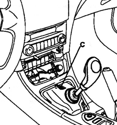
Note: You can move the automatic transmission selector lever by pressing button C, located in front of it.
Installation
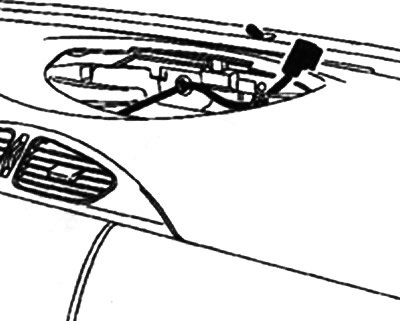
Before installing the instrument cluster, route and connect the tweeter, display, and solar sensor wire harnesses.
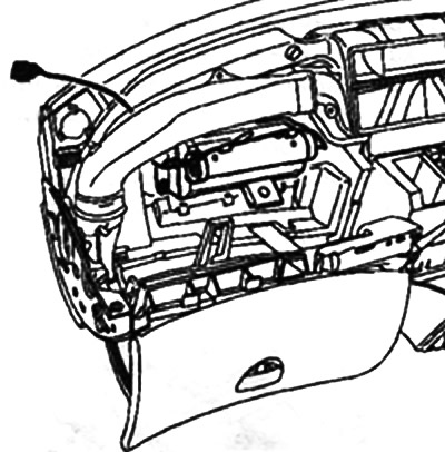
Connect the passenger airbag wiring harness.
Features of the contact disk
Make sure the wheels are set in the straight ahead position.
Check that the contact disk is installed correctly; the "O" mark on the contact disk should be opposite the pointer.
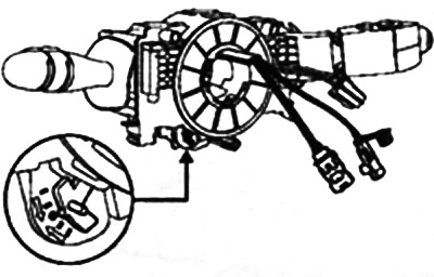
Features of the instrument panel visor
Install the instrument cluster and lower steering column trim.
Install the top trim cover, positioning the leather trim as shown in the picture (see below).
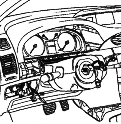
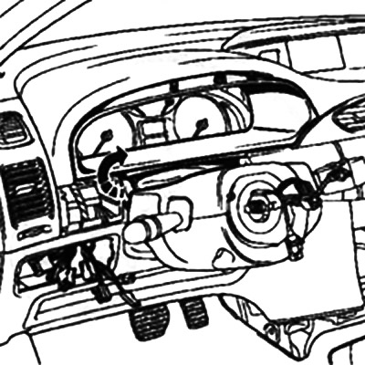
Attach the instrument panel visor.
Apply the adhesive tape of the upper trim cover to the visor.
Fix the visor to the dashboard.
Steering wheel features
Attention! There are special guides in the steering wheel grooves. The steering wheel should fit freely into the grooves. Try not to damage the grooves.
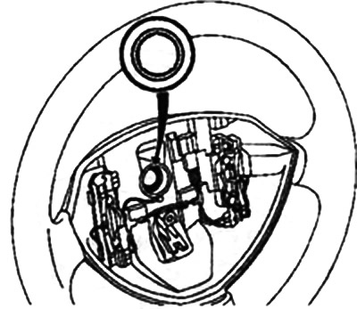
After each removal, be sure to replace the steering wheel mounting bolt and tighten it to 44 Nm.