
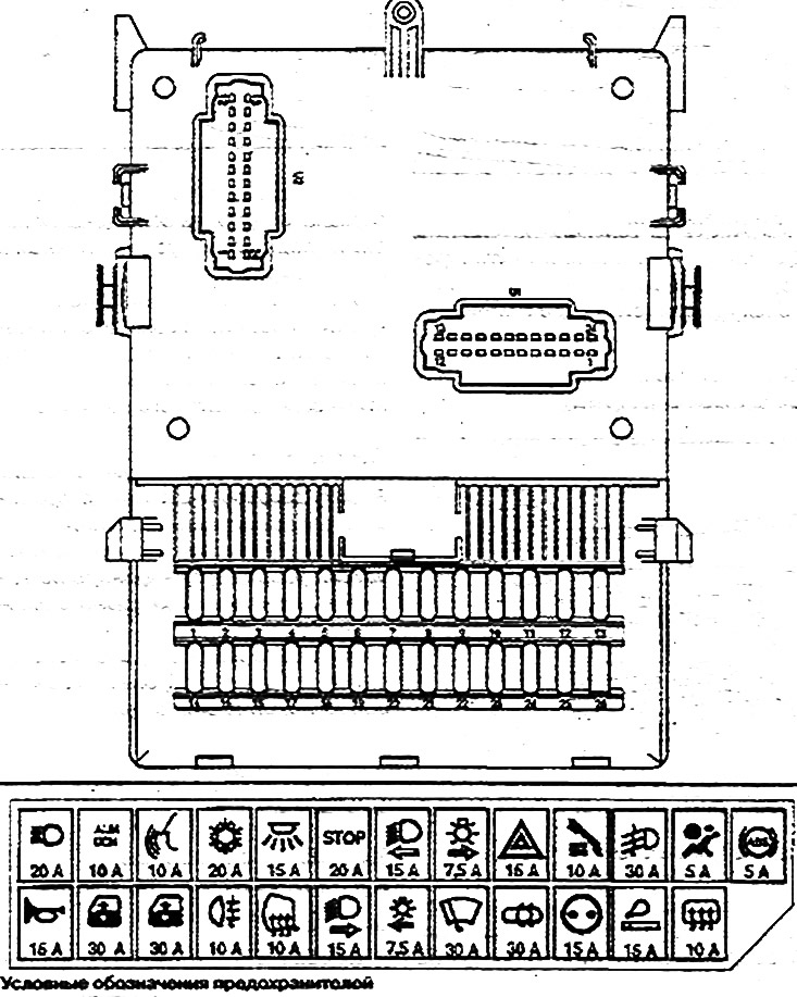
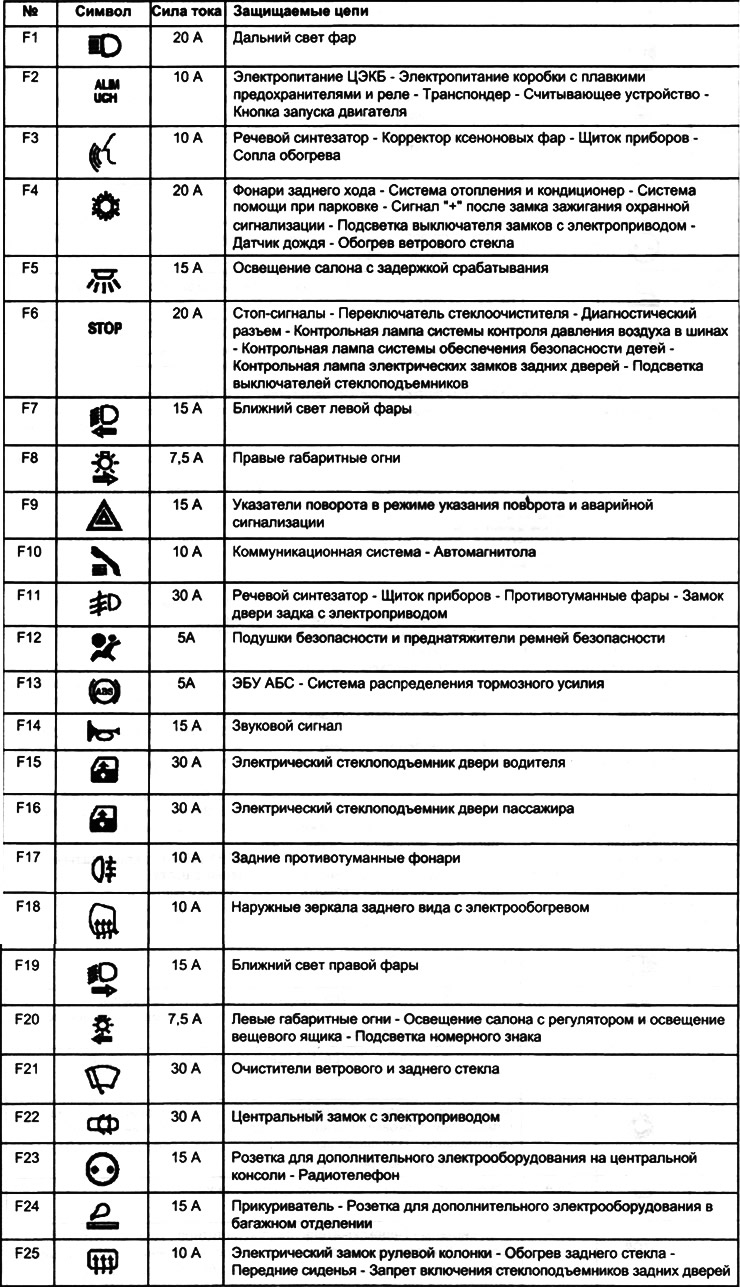
Circuits protected by fuses (depending on equipment level)
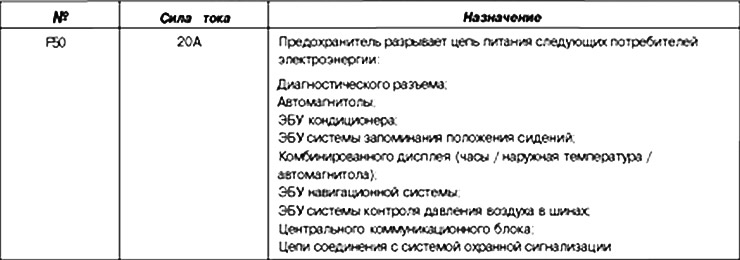
Fuse for disconnecting consumers of electricity
U1 (24 pin connector):
- 1. Central locking exit.
- 2. The output of the central lock.
- 3. Input of the parallel target of the left front position light.
- 4. Not used.
- 5. Input of a parallel chain of the right forward dimensional light.
- 6. License plate light parallel circuit input.
- 7. Input of a circuit of failure of a safety lock of the right dimensional lights.
- 8. Input of a circuit of failure of a safety lock of the left dimensional lights.
- 9. Not used.
- 10. Input low beam headlights.
- 11. Input of a parallel chain of the right back dimensional light.
- 12. Not used.
- 13. Not used.
- 14. Power supply input of the electronic fuse/relay box.
- 15. Not used.
- 16. Brake lights failure circuit input.
- 17. Input of a parallel chain of the left back dimensional light.
- 18. Not used.
- 19. Left brake light parallel circuit input.
- 20. Entrance of the central lock.
- 21. Right brake light parallel circuit input.
- 22. Stoplight switch input.
- 23. The output of the central lock.
- 24. The output of the central lock.
U2 (24-pin connector):
- 1. Rear window wiper relay output.
- 2. Login «+» after the ignition switch through the relay (key with code).
- 3. Login «+» after ignition switch, home position, via relay (key with code).
- 4. Exit «+» after the ignition switch through the relay (key with code).
- 5. Power input of the central lock.
- 6. Not used.
- 7. Not used.
- 8. Relay output for opening doors with central locking.
- 9. Auxiliary electrical equipment relay output 2
- 10. Relay output for closing doors with central locking.
- 11. Auxiliary electrical equipment relay output 1.
- 12. Turn signal input.
- 13. Turn signal input.
- 14. Not used.
- 15. Output circuit for turning on the left turn signal.
- 16. Input for diagnostics of the direction indicator.
- 17. The output of the circuit for turning on the right turn signal.
- 18. Windshield wiper low and high speed relay output.
- 19. Turn signal power input.
- 20. Windshield wiper on/off relay output.
- 21. Engine start inhibit relay output.
- 22. Entrance side lights.
- 23. Delayed power relay output.
- 24. Entrance of the litany of the TsEKB.
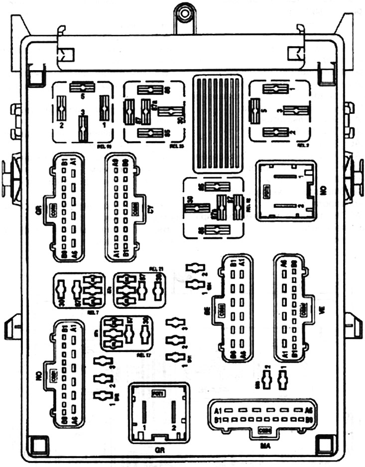
CGB1 (15-pin black connector);
- white color
- A1. Not used.
- A2. «+ «fog lights.
- A3. «+» fog lamp relay.
- A4. Not used.
- A5. Not used.
- A6. «+» battery, with fuse through passenger compartment 1 (caravan connection).
- Black color
- 81. «+» battery (through the fuse), central locking.
- 82. «+» after the ignition switch (through the fuse), ABS/trajectory stabilization systems.
- 83. «+» after the ignition switch (through the fuse), airbag system.
- 84. Not used.
- 85. «+» electricity consumers (through the fuse).
- 86. Not used.
- 87. «+» electricity consumers (through the fuse).
- 88. «+» electricity consumers (through the fuse).
- 89. «+» electricity consumers (through the fuse).
CGB2 (15-pin gray connector):
- white color
- A1. «+» battery (through the fuse) (air conditioner).
- A2. «+» battery (through the fuse) (air conditioner).
- A3. «+» electricity consumers (through the fuse).
- A4. «+» central locking control circuit.
- A5. «+» the purpose of controlling the door unlocking using the central locking.
- A6. Weight.
- Black color
- 81. «Weight».
- 82. Management of unlocking the rear door from the inside / outside.
- 83. Control of locking the rear door from the driver's side from the outside.
- 84. Management of locking the rear door from the inside.
- 85. Management of locking the rear door from the inside.
- 86. Management of unlocking from the outside of the rear doors on the driver's side and unlocking from the inside of the front doors.
- 87. Management of unlocking from the outside of the rear doors on the driver's side and unlocking from the inside of the front doors.
- 88. Not used.
- 89. «+» luggage compartment lighting timing relay control circuit.
CGB3 (Brown 15-pin connector):
- white color
- A1. «+» dipped headlights.
- A2. Not used.
- AZ. «+» turn on high beam headlights.
- A4. Not used.
- A5. «+» Control (through the fuse) sound signal.
- A6. «+» Control (through the fuse) rear fog lamps.
- Black color
- 81. «Weight».
- 82. «+» low beam right headlight «+» low beam left headlight.
- 83. «+» Control (through the fuse) heated exterior mirrors.
- 84. «+» Control (through the fuse) rear fog lamps.
- 85. Not used.
- 86. «+» consumers of electricity / battery (through the fuse), windows for the driver's and passenger's doors.
- 87. «-» interior lighting control.
- 88. «+» battery (through the fuse), window lifters.
- 89. «+» sound signal control.
CGB4 (15-pin green connector):
- white color
- A1. «+» high beam control (through the fuse).
- A2. Rear door lock relay coil control.
- AZ. After the ignition switch or battery, rear power window.
- A4. Rear power window relay control.
- A5. Not used.
- A6. «+» rear window heating control.
- Black color
- 81. «+» battery (through the fuse), transceiver unit.
- 82. Not used.
- 83. «+» after the ignition switch (through the fuse), additional electrical equipment.
- 84. «+» rear window wiper control.
- 85. Not used.
- 86. «+» time relay control for interior lighting.
- 87. «+» control of the right rear marker light.
- 88. «+» control of the right front position light.
- 89. «-» control of the heated rear window relay.
CGB5 (Blue 12-pin connector):
- white color
- A1. «+» battery with fuse, through the passenger compartment 3.
- A2. Not used.
- AZ. «+» after the ignition switch.
- A4. «+» battery (through the fuse), central locking.
- A5. Not used.
- A6. «+» battery with fuse, through the passenger compartment 2.
- Black color
- 81. «Weight».
- 82. «+» high beam headlights.
- 83. «+» starter.
- 84. Relay control side lights.
- 85. Not used.
- 86. Low beam relay control.
CGB6 (18-pin connector transparent):
- white color
- A1. Not used.
- A2. «+» after the ignition switch (through the fuse), rear window heating control.
- AZ. «+» after the ignition switch (through the fuse), rear window heating control.
- A4. Not used.
- A5. Not used.
- A6. Not used.
- A7. «+» control of the relay-interrupter of direction indicators and alarms.
- A8. Control of left turn indicators.
- A9. Control of right turn indicators.
- Black color
- 81. «+» control of the windshield wiper operation with a time relay at low speed.
- 82. «+» control of the windshield wiper operation with a time relay at high speed.
- 83. «+» after the ignition switch (through the fuse), brake lights.
- 84. «+» license plate lighting control.
- 85. «+» control of the left rear marker light.
- 86. «+» control of the right rear marker light.
- 87. Stop lamp control.
- 88. «+» control of the right brake light.
- 89. «+» left brake light control.
- REL2. Rear window heating relay.
- REL7. Fog lamp relay.
- REL9. Windshield wiper relay.
- REL10. Windshield wiper relay.
- REL11. Relay for rear window wiper/ reversing lights.
- REL12. Relay locking opening elements.
- REL13. Relay locking opening elements.
- REL17. Rear window wiper relay.
- REL18. Interior lighting relay with delay.
- REL19. Auxiliary relay.
- REL21. Engine start inhibit relay.
- REL22. Relay of the central electronic switching unit / «+ «after the ignition switch.
- REL23. Relay of additional electrical equipment, car radio (aftermarket rear power window installation).
- SH1. Rear power window jumper.
- SH2. Front power window jumper.
- SH3. Jumper headlights daytime running.
- SH4. Jumper headlights daytime running.
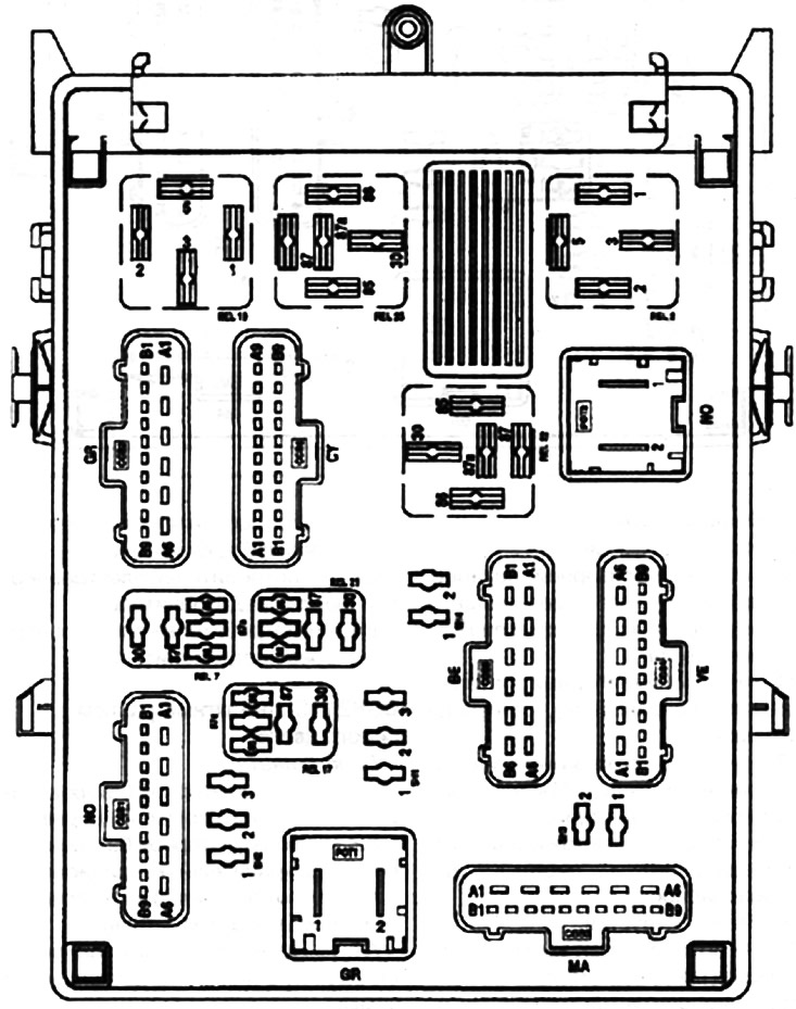
Note. This fuse box is located on the fuse and relay box.
Note. The additional fuse and relay box is located on the passenger side in front of the glove box.