English Русский
Български
Беларускі
Український
Српски
Hrvatski
Română
Polski
Slovenský
Magyar
Bookmark Contacts Articles Sitemap
Company vehicles Peugeot Company vehicles Opel Company vehicles Skoda Company vehicles Land Rover Company vehicles Mitsubishi Company vehicles Volkswagen Company vehicles Honda
RenaultBook.ru


Duster   Fluence   Kangoo   Laguna   Logan   Megane   Sandero   Scenic   Symbol   Clio   Other
Logan 1 (2004-2012, petrol) Logan 2 (2012-2020)

Fuel tank and fuel lines (Renault Logan 2)

  • Main
  • Logan
  • Logan 2 (2012-2020)
  • Power unit
  • Power and control system
  • Fuel tank and fuel lines
0
Contents: Fuel tank 🠛 Removal and installation the fuel…🠛 Removal and installation the fuel…🠛
Attention:
  • When working on the fuel tank or fuel lines, smoking or using open flames in the workplace is not permitted.
  • Be careful not to spill fuel when disconnecting the fuel connectors.
  • When performing work, use leak-resistant nitrile gloves and goggles with side protection.
  • To prevent contaminants from entering the fuel system circuit, use plugs to seal the openings of disconnected components.
  • To avoid corrosion or damage, measures must be taken to protect surfaces that may come into contact with leaking fuel.


Fuel tank


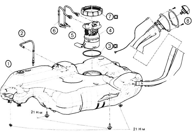
1. Fuel tank. 2. Fuel vapor line. 3. Fuel level sensor module gasket. 4. Fuel level sensor module.…

1. Fuel tank. 2. Fuel vapor line. 3. Fuel level sensor module gasket. 4. Fuel level sensor module. 5. Fuel supply line. 6. Fuel return line. 7. Fuel level sensor module mounting ring. 8. Filler cap.


Note: replace the part with a new one after each removal.


Draining fuel from the tank


1. Place the vehicle on a two-post lift.


2. Disconnect the negative battery terminal.

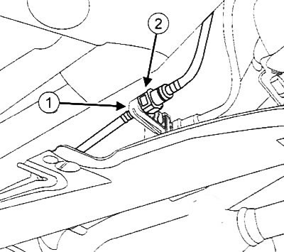
3. Disconnect the fuel supply line connector from the holder (1).

3. Disconnect the fuel supply line connector from the holder (1).


4. Disconnect the fuel supply line connector (2).

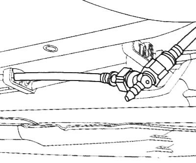
5. Install the T-piece from the fuel pressure measuring kit (Mot. 1311-08).

5. Install the T-piece from the fuel pressure measuring kit (Mot. 1311-08).


6. Connect the pneumatic fuel pump to the T-piece

7. Prepare a container to collect leaking fuel.

8. Drain the fuel from the tank

9. Remove all installed components in the reverse order of installation

Removal and installation the fuel tank


Removal the fuel tank


1. Place the vehicle on a two-post lift.

2. Disconnect the negative battery terminal.

3. Drain the fuel from the tank (see above).

4. Remove the rear right wheel.

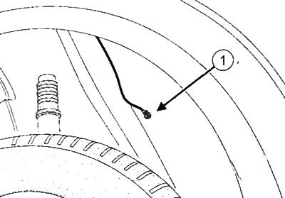
5. Disconnect the ground cable (1) from the vehicle body.


5. Disconnect the ground cable (1) from the vehicle body.


6. Remove the elastic element of the intermediate pipe.

7. Disconnect the parking brake cables from the fuel tank (4).
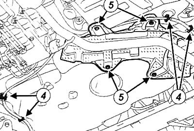
7. Disconnect the parking brake cables from the fuel tank (4).


8. Remove the fasteners (5) of the fuel tank heat shield.

9. Remove the fuel tank heat shield.

10. Disconnect the quick-release connectors of the fuel tank line terminals.

Caution: To prevent contamination from entering the power supply circuit, place protective plugs on the openings of the removed components.


11. Install plugs on the fuel lines.

12. Loosen the filler neck mounting bolts.

13. Loosen the fuel tank mounting nuts.

14. Loosen the fuel tank mounting bolts.

15. Lower the fuel tank slightly.

16. Disconnect the fuel pump connector.

Note: Two people are needed to perform the following operation.


17. Remove the fuel tank from the vehicle.

Installing a fuel tank


Installation is carried out in the reverse order of removal.

Removal and installation the fuel module (fuel level sensor unit with fuel pump)


Removal the fuel module


1. Using the diagnostic module, perform the pre-repair procedure by selecting "Injection computer" (injection control processor) and "Low pressure fuel pump" (low pressure fuel pump).

2. Disconnect the negative battery terminal.

3. Remove the rear seat cushion of the car.

4. Partially remove the rear door seals.

5. Remove the rear center mat.

6. Using the tools from the trim removal kit (Car. 1363), remove the plug from the service hole.

Note: Prepare for possible fuel leakage from the supply and return fuel lines.


7. Disconnect the electrical connector from the fuel module.

8. Disconnect the fuel line connectors from the fuel module.

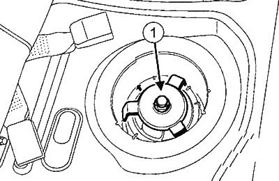
9. Using the universal wrench (Mot. 1397) (1), unscrew the fuel module nut.

9. Using the universal wrench (Mot. 1397) (1), unscrew the fuel module nut.


10. Remove the fuel module, being careful not to damage the float.

Caution: To avoid deformation of the fuel tank, it is necessary to immediately install the fuel module mounting nut back into place.


Installing the fuel module


1. Correctly place the gasket (7) in the neck.
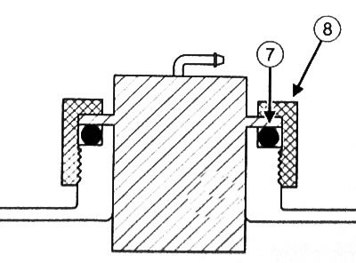
1. Correctly place the gasket (7) in the neck.


2. Insert the fuel module into the tank. To ensure that only one installation position is possible, there is a protrusion on the module and a recess in the tank.

Note: The mark (9) on the fuel module must be located opposite the mark (11) on the fuel tank.
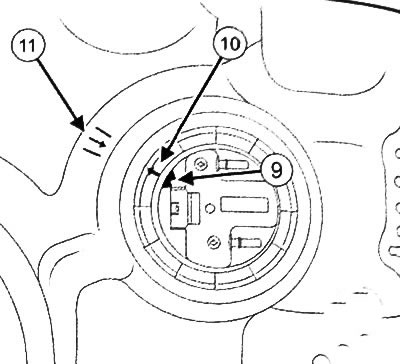

Note: The mark (9) on the fuel module must be located opposite the mark (11) on the fuel tank.


3. Press the fuel module by hand (to prevent the gasket from shifting) and tighten the mounting nut.

4. Using the universal wrench (Mot. 1397), tighten the nut (8) until the mark (10) on the nut aligns with the mark (11) on the fuel tank.

5. Connect the fuel lines to the fuel module connectors.

6. Connect the electrical connector of the fuel module.

7. Install the plug into the service hole of the fuel module.


8. Install the rear center mat.

9. Install door seals.

10. Install the rear seat cushion.

11. Connect the battery.

Checking the fuel level sensor


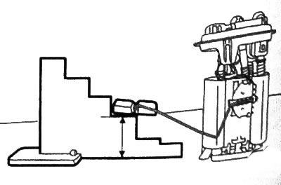
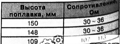
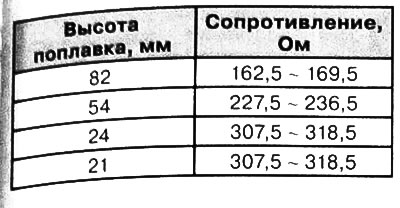
1. Remove the fuel module (see above).

2. Make sure that the resistance value of the sensor changes as the position of the float changes.

2. Make sure that the resistance value of the sensor changes as the position of the float changes.


Checking the fuel level sensor


1. Remove the fuel module (see above).

2. Make sure that the resistance value of the sensor changes as the position of the float changes.

2. Make sure that the resistance value of the sensor changes as the position of the float changes.

2. Make sure that the resistance value of the sensor changes as the position of the float changes.
This article is available on: russian, bulgarian, belarusian, ukrainian, serbian, croatian, romanian, polish, slovak, hungarian
Article has been reviewed by editor: Petrovsky Roman
Share with friends:
 
Logan 2: Power and control system
Next

 
Fuel lines of the fuel system
Fuel system of the D4F engine (1.2 l)
Fuel system of K7M and K4M engines (1.6 l)
Removal and installation of fuel rail with injectors, K7M engine (1.6…
Removal and installation of fuel rail with injectors, K4M engine (1.6…
Other articles on other Renault models

➽ Fuel tank Renault Duster 1 (2009-2017)
➽ Fuel tank (all engines) Renault Fluence 1 (2009-2020, petrol)
➽ Fuel tank Renault Kangoo 1 (1997-2007)
➽ Fuel tank — design description Renault Laguna 2 (2001-2007)
➽ Removal and installation the fuel tank Renault Megane 1 (1995-2002)
Link to this article in different formats
Reviews and comments of visitors
No comments yet


Add two numbers 40 + 20


Logan 2 (2012-2020) 
  • General information
  • Faults en route
  • Daily checks
  • Governing bodies
  • Maintenance
  • Power unit
  • Petrol engines 1.2 l
  • Petrol engines 1.6 l
  • Diesel engines 1.5 l
  • Cooling system
  • Lubrication system
  • Power and control system
  • Intake and exhaust system
  • Engine electrical equipment
  • Transmission
  • Clutch
  • Car gearbox
  • Drive shafts
  • Chassis, running gear
  • Suspension and wheels
  • Brake system
  • Steering
  • Body and interior
  • Exterior (external elements)
  • Interior (internal elements)
  • Safety system
  • Heating and air conditioning
  • Electrical equipment
  • Equipment and devices
  • Wiring diagrams (sedan)
  • Wiring diagrams (wagon)
Logan 1 (2004-2012, petrol) 
  • General information
  • Vehicle device
  • User manual
  • Faults en route
  • Daily maintenance
  • First maintenance
  • Second maintenance
  • Driver tips
  • Power unit
  • Engine repair
  • Lubrication system
  • Cooling system
  • Power and exhaust system
  • Transmission
  • Clutch
  • Car gearbox
  • Drive shafts
  • Chassis, running gear
  • Front suspension
  • Rear suspension
  • Steering
  • Brake system
  • Wheels and tires
  • Body and interior
  • Exterior (external elements)
  • Interior (internal elements)
  • Doors, locks and windows
  • Body Care
  • Electrical equipment
  • Equipment and devices
  • Headlights and lighting
  • Power devices
  • Electrical circuits
RenaultBook.ru © 2018–2026 | Mobile version | News and articles | Sitemap: EN BG BY UA RS HR RO PL SK HU | Administration | Site search | Bookmark
Duster 1 (2009-2017) | Fluence 1 (2009-2020, petrol) | Kangoo 1 (1997-2007) | Laguna 2 (2001-2007) | Logan 1 (2004-2012, petrol) | Logan 2 (2012-2020) | Megane 1 (1995-2002) | Megan 2 (2002-2009, petrol) | Sandero 1 (2007-2012, petrol) | Scenic 1 (1996-2003) | Symbol 1 (1999-2008, petrol) | Symbol 2 (2008-2013, petrol) | Renault 19 (1988-1996) | Espace I and II (1984-1996) | Espace III (1996-2002) | Clio 1 (1990-1998) |
We want your visit to be comfortable 😌 and use cookies 🍪 to do so.